
Over-Mount Corner

a corner and over-mount technology, applied in the field of over-mount corners and quoin corners, can solve the problems of substantial material waste and loss of operating efficiency, and achieve the effect of quick and easy installation

Active Publication Date: 2009-09-24
BORAL STONE PRODS
View PDF28 Cites 12 Cited by
  • Summary
  • Abstract
  • Description
  • Claims
  • Application Information

AI Technical Summary

Benefits of technology

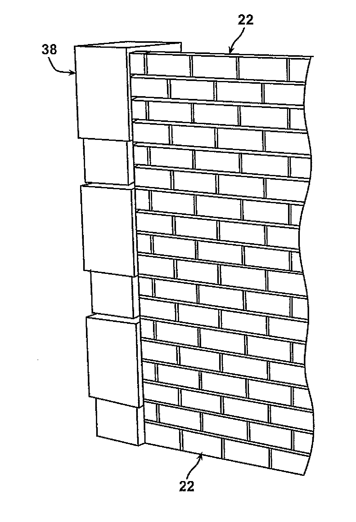
[0033]It is an advantage of the present invention that the over-mount corner units are quickly and easily installed.
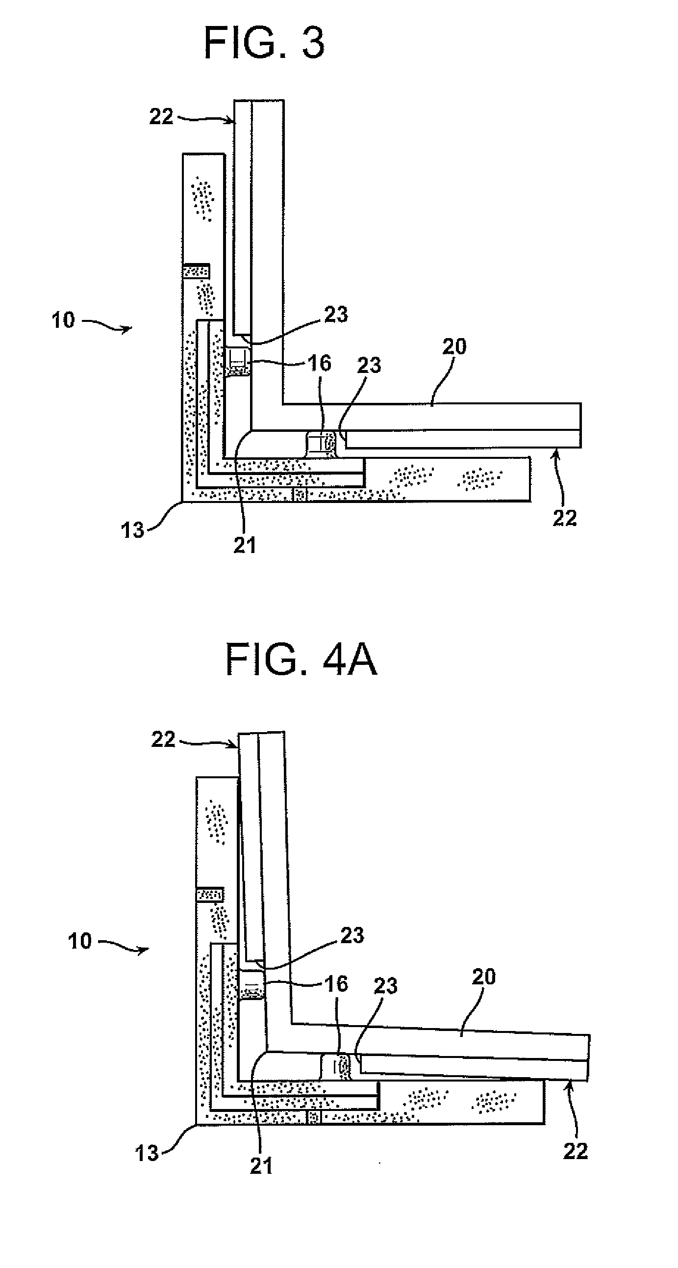
[0034]It is another advantage of the present invention that the over-mount coiner units can compensate for variations in the angle of the walls forming the exterior corner of a building or residential structure.
[0035]It is a further advantage of the present invention that the over-mount corner units overlap the wall panels at the exterior corner of the building substructure.
[0036]It is another advantage of the present invention that the wall panels do not require precise cutting to define the terminus of the wall panels near the exterior coiner of the building substructure.
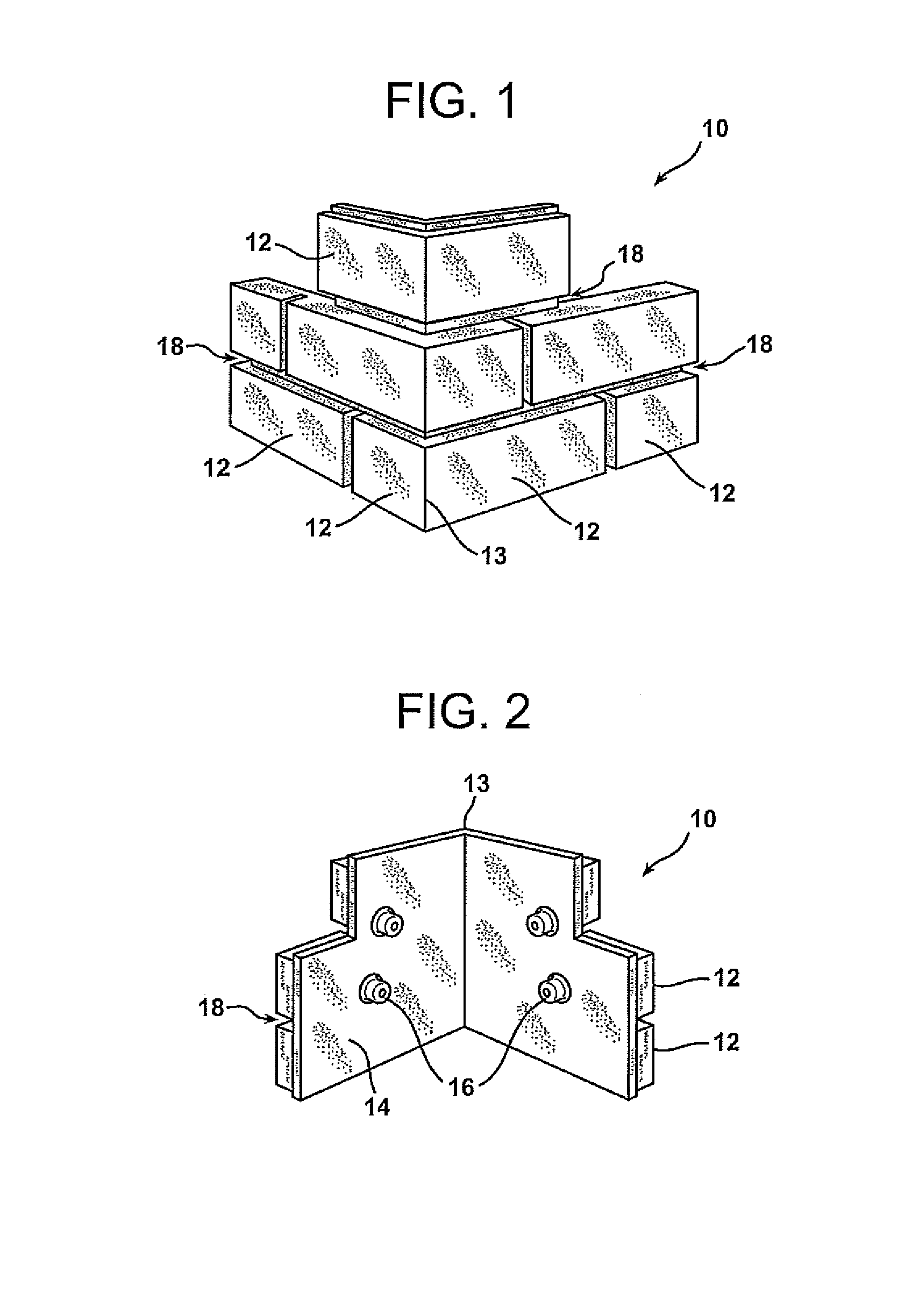
[0037]It is still another advantage of this invention that the standoffs are located opposite a joint between vertically spaced simulated bricks to permit the fastener head to be hidden within the corner unit.
[0038]It is yet another advantage of this invention that the fastener head can be covered with mortar for purposes of concealment.

Problems solved by technology

These walls require an external covering to keep rain, snow, sunlight, and other environmental factors off of the wall substructure, particularly when the sheathing material is formed of oriented strand board (OSB) or other products that are not tolerant to being in contact with significant amounts of moisture.
The time required to make this proper fit for the brick or stone panels resulted in lost operating efficiency, as well as substantial material waste if the panels did not precisely fit together to provide an aesthetically pleasing appearance.

Method used


Image

  • Over-Mount Corner
  • Over-Mount Corner
  • Over-Mount Corner

Examples


Embodiment Construction

[0060]Unless defined otherwise, all technical and scientific terms used herein have the same meaning as commonly understood by one of ordinary skill in the art to which the invention belongs. All references cited herein, including published or corresponding U.S. or foreign patent applications, issued U.S. or foreign patents, or any other references, are each incorporated by reference in their entireties, including all data, tables, figures, and text presented in the cited references.

[0061]In the drawings, the thickness of the lines, layers, and regions may be exaggerated for clarity. It is to be noted that like numbers found throughout the figures denote like elements. It will be understood that when an element is referred to as being “on,” another element, it can be directly on or against the other element or intervening elements may be present.

[0062]The present invention relates to projected quoin corners that mount over simulated, external panels positioned on a residential dwell...


PUM


Abstract

A quoin formed of individual over-mount corner units constructed as simulated brick to match the adjoining wall panels forming the exterior cover of an exterior wall of a building is provided. The corner units are formed with a front portion configured as courses of brick separated by mortar joints joined to a rear plate that provides a support frame for the corner unit. Multiple standoffs are positioned on the rear plate opposite mortar joints formed on the front portion to provide a location for driving fasteners to mount the corner unit onto the building substructure. The overlapping nature of the corner units with respect to the wall panels allows the wall panels to be cut imprecisely at the exterior corner. The standoffs maintain a predetermined spacing between the building substructure and the rear plate to establish a channel for the drainage of moisture due to condensation or rain infiltration.

Description

TECHNICAL FIELD AND INDUSTRIAL APPLICABILITY OF THE INVENTION[0001]The present invention relates generally to simulated panels, and more particularly, to a quoin corner that mounts over simulated panels to provide an aesthetic appearance to a residential dwelling or other habitable building.BACKGROUND OF THE INVENTION[0002]Most habitable buildings are made of vertical support members formed from wood or metal studs. These vertical support members form a substructure on which sheets of sheathing material are attached to form the walls of the building substructure. These walls require an external covering to keep rain, snow, sunlight, and other environmental factors off of the wall substructure, particularly when the sheathing material is formed of oriented strand board (OSB) or other products that are not tolerant to being in contact with significant amounts of moisture. Another covering for the wall substructure that is often selected is a covering formed of a masonry construction, ...

Claims


Application Information

Patent Timeline
IPC IPC(8): E04F19/06
CPCE04F13/147E04F19/061E04F19/024E04F13/0736E04F13/148
Inventor TYLER, FRANCIS S.HINES, DAVID C.WOLF, DAVID H.BROEHL, JOSHUA M.FLOAT, JAMISON J.LUA, JAMES H.
Owner BORAL STONE PRODS
Learn More