Magnetically actuated roller head

a technology of magnetic actuators and roller heads, which is applied in the direction of propulsion systems, metal-working machine components, manufacturing tools, etc., can solve the problems of increasing the cost, size, and complexity of a conventional roller hemming head

Inactive Publication Date: 2009-09-24
HIROTEC AMERICA
View PDF40 Cites 15 Cited by
  • Summary
  • Abstract
  • Description
  • Claims
  • Application Information

AI Technical Summary

Benefits of technology

[0004]The present invention provides a magnetically actuated roller hemming head that utilizes magnetic and/or electromagnetic force to actuate a roller hemming head and to provide a hemming force through a hem roller of the roller hemming head. The present invention may allow for variable fo

Problems solved by technology

These requirements may elevate the cost, size, and

Method used


Image

  • Magnetically actuated roller head
  • Magnetically actuated roller head
  • Magnetically actuated roller head

Examples


first embodiment

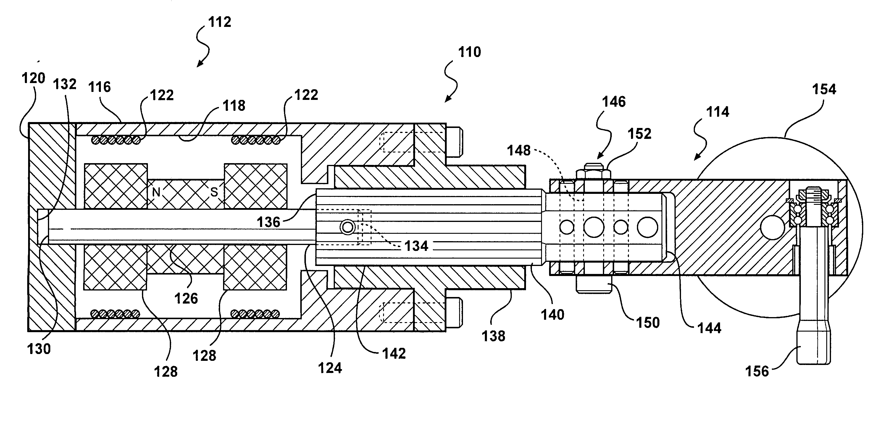
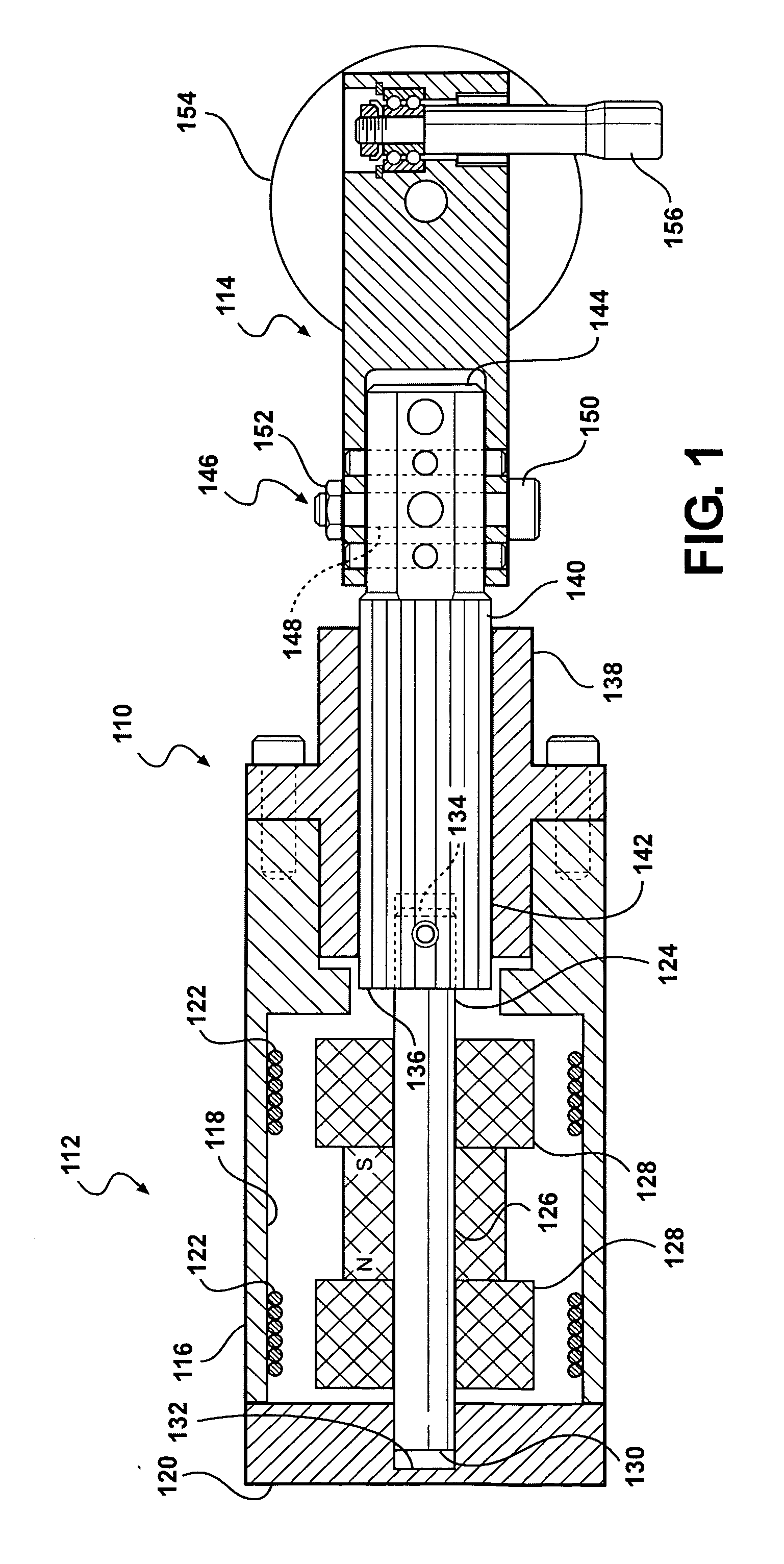
[0022]With reference to FIG. 1, in a first embodiment the magnetically actuated roller head 110 includes a linear actuator 112 mountable on an end of a multi-axis robotic arm (not shown). A roller hemming head 114 is mounted on the linear actuator 112. The linear actuator 112 provides a hemming force for performing roller hemming operations with the roller hemming head 114.

[0023]The linear actuator 112 includes a housing 116 that has an inner bore 118 that generally extends through the housing. An end cap 120 is mounted on an end of the housing 116 and closes an end of the inner bore 118. The end cap 120 may include a feature such as a mounting surface for mounting the linear actuator 112 on a robotic arm.

[0024]A pair of opposing actuator members 122 are fixedly mounted within the inner bore 118. A shaft 124 extends through the actuator members 122. A magnet 126 is mounted on the shaft 124 and is moveable within the inner bore 118. The magnet 126 is disposed between the actuator mem...
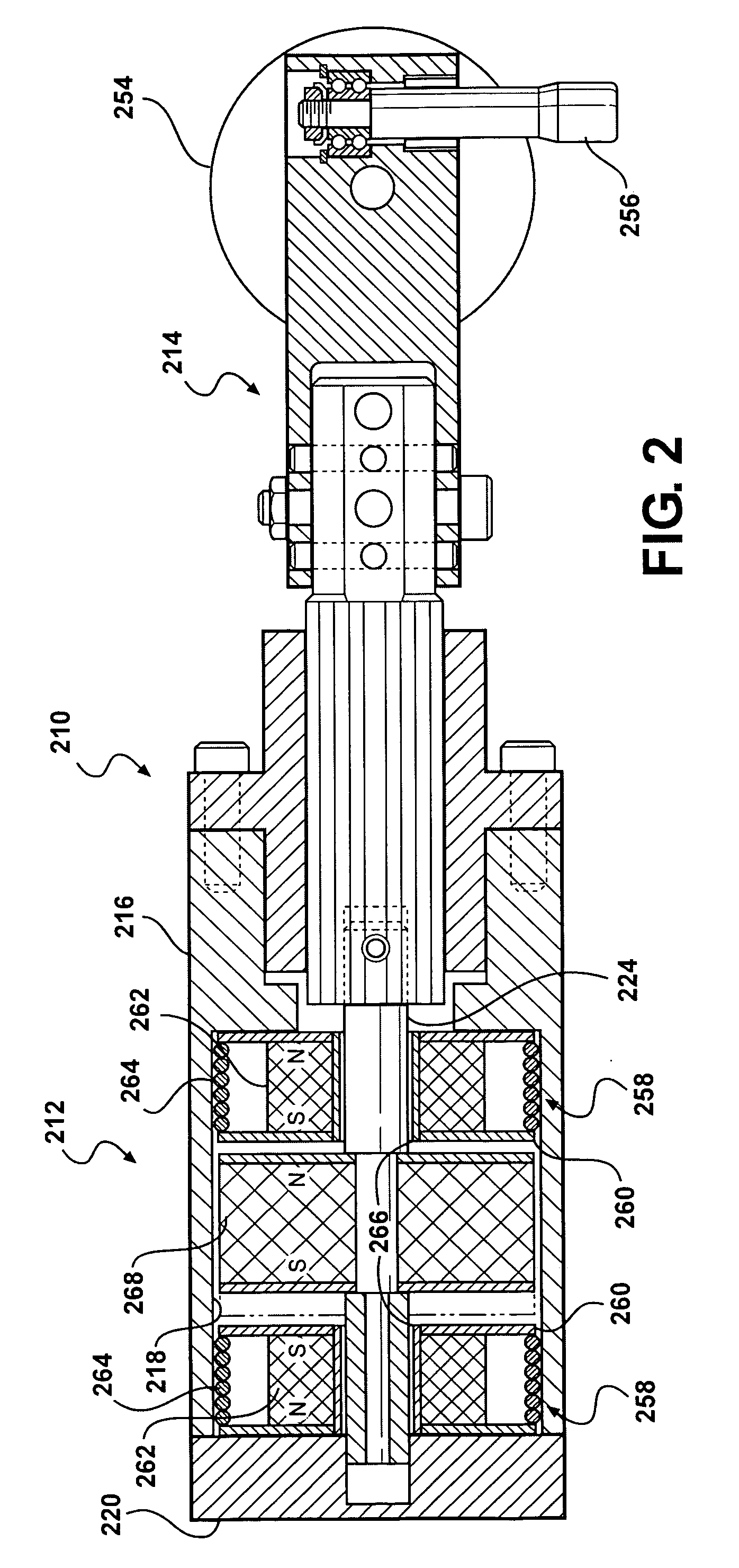
third embodiment

[0037]In the third embodiment, the housing 316 and shaft 324 may be non-magnetic so as to not interfere or interact with the magnetic field of the rare earth magnets.


PUM

PropertyMeasurementUnit
Forceaaaaaaaaaa
Polarityaaaaaaaaaa

Abstract

A magnetically actuated roller head includes a linear actuator mountable on an end of a multi-axis robotic arm. The linear actuator includes a slide, a magnet operably connected to the slide and operable to urge the slide in a linear direction, and a connector disposed on a distal end of the slide. A roller hemming head is mounted on the linear actuator by the connector. The roller hemming head includes at least one hem roller.

Description

CROSS REFERENCE TO RELATED APPLICATION[0001]This application claims the priority of U.S. Provisional Application No. 61 / 070,551 filed Mar. 24, 2008.TECHNICAL FIELD[0002]This invention relates to robotic roller hemming, and more particularly a robotic roller head used for robotic roller hemming such as hemming of vehicle closure panels.BACKGROUND OF THE INVENTION[0003]It is known in the art relating to actuation of a roller hemming head that conventional actuators typically require one or more of the following: hydraulics, pneumatics, electric cylinders, gas spring charge, monitoring of air or gas pressure, and oil disposal. These requirements may elevate the cost, size, and complexity of a conventional roller hemming head.SUMMARY OF THE INVENTION[0004]The present invention provides a magnetically actuated roller hemming head that utilizes magnetic and / or electromagnetic force to actuate a roller hemming head and to provide a hemming force through a hem roller of the roller hemming h...

Claims


Application Information

Patent Timeline
IPC IPC(8): B21D39/02B21D19/04
CPCB21D39/021B21D39/023Y10T29/53996H02K41/03Y10T29/53787H02K33/16
Inventor TOENISKOETTER, JAMES
Owner HIROTEC AMERICA
Why Eureka
Try Eureka