Flow rate control device

Active Publication Date: 2009-09-24
CKD
View PDF4 Cites 12 Cited by
  • Summary
  • Abstract
  • Description
  • Claims
  • Application Information

AI Technical Summary

Benefits of technology

[0028]In the present teaching, the regulator and the open/close section can be controlled by the controller. When the control flow rate by the regulator is small, the open/close section can be placed in the closed position by the controller, and when the control flow rate by the regulator is large, the open/close section

Problems solved by technology

However, with the aforementioned technology that can change the valve opening of the orifice by means of a motor, a comparatively long period of time will be needed to change the valve opening when the flow rate of a fluid is to be changed.
As a result, when high cost liquid chemicals

Method used


Image

  • Flow rate control device
  • Flow rate control device
  • Flow rate control device

Examples


Embodiment Construction

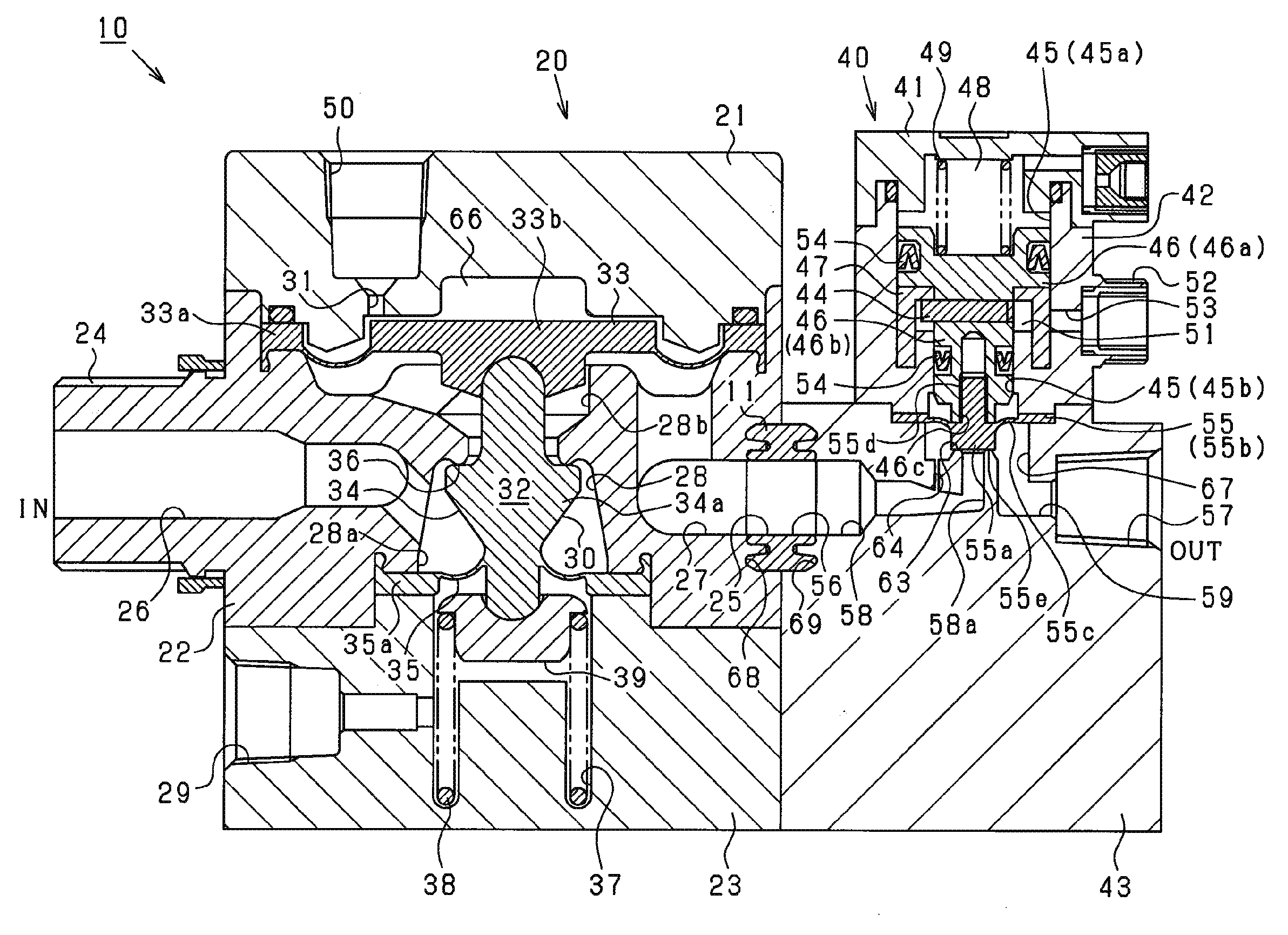
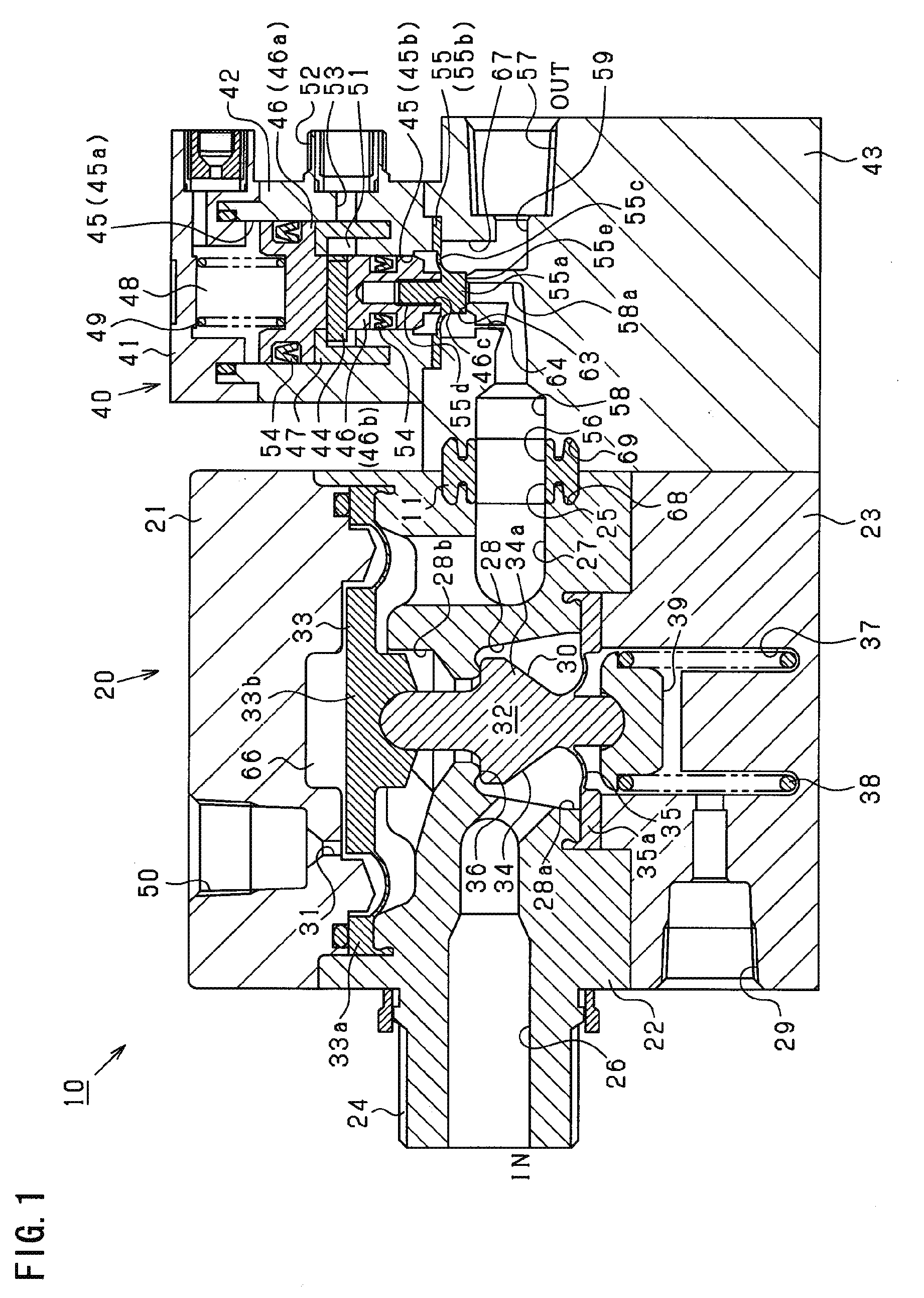
[0034]An embodiment of a flow rate control device used for liquid chemical supply on a semiconductor manufacturing line will be explained below with reference to the drawings. FIG. 1 is a vertical cross-section showing the construction of a flow rate control device 10.

[0035]As shown in FIG. 1, the flow rate control device 10 comprises a pilot regulator 20 as a pressure adjustment means, and an air operate valve 40 arranged on the downstream side thereof, with these being integrally attached together by means of fastening members such as bolts.

[0036]The pilot regulator 20 is formed by integrally attaching an upper cover 21, a body 22, and a lower cover 23 together in this order by means of fastening members such as bolts, with its overall shape approximating a rectangle. Note that the body 22 is formed for example from a fluorine resin, and the covers 21, 23 are for example formed from a polypropylene resin.

[0037]An intake port 24 for drawing in fluid, and a supply port 25 for supply...


PUM


Abstract

A flow rate control device comprises a regulator that adjusts the pressure of a fluid to be supplied, a plurality of narrowed pathways arranged in parallel on the downstream side of the regulator, and an open/close section that switches a predetermined narrowed pathway amongst the plurality of narrowed pathways between an open position and a closed position. One of the pathways can be an open narrowed pathway arranged on the downstream side of the regulator and another can be an opened/closed narrowed pathway arranged downstream of the regulator in parallel with the open narrowed pathway. In this case, the open/close section that switches the opened/closed narrowed pathway between as open position and a closed position.

Description

[0001]The present application claims priority based on Japan Patent Application No. 2008-072264 filed on Mar. 19, 2008, and the entire contents of that application is incorporated by reference in this specification.FIELD OF THE INVENTION[0002]The present invention relates to a flow rate control device that controls the flow rate of fluids.BACKGROUND OF THE INVENTION[0003]A flow rate control device is used to adjust the flow rate of fluids such liquid chemicals in semiconductor manufacturing devices, and is also employed in the pharmaceutical and chemical fields when mixing liquids in desired ratios.[0004]In this type of flow rate control device, it is known to arrange an orifice on the downstream side of a regulator. With this flow rate control device, the flow rate of a fluid is controlled by controlling the primary pressure of the orifice (i.e., the secondary pressure of the regulator) by means of the regulator (see for example Patent Reference 1).[0005]However, with the flow rate...

Claims


Application Information

Patent Timeline
IPC IPC(8): F16K15/00
CPCG05D7/0635Y10T137/7838Y10T137/7762F16K31/365F16K17/04G05D11/02B01F35/80
Inventor SUGATA, KAZUHIROKATO, TAKASHI
Owner CKD
Why Eureka
Try Eureka