Battery case for electric vehicle

a battery case and electric vehicle technology, applied in the field of battery cases, can solve the problems of unstable tightening torque of the bolt screwed into the nut, inability to accurately control torque, and difficulty in inserting the embedded bolt into the hole formed at predetermined positions of the die, so as to prevent the sealing adversely affect the torque control of the threaded part.

Inactive Publication Date: 2009-09-24
MITSUBISHI MOTORS CORP
View PDF10 Cites 103 Cited by
  • Summary
  • Abstract
  • Description
  • Claims
  • Application Information

AI Technical Summary

Benefits of technology

[0012]The present invention provides a battery case that makes it possible to prevent a seal member to be provided at a joint part between a tray member and a cover member from adversely affecting the torque control of the threaded part, and makes it easy to set an insert member in a die for molding the tray member.
[0015]According to the present invention, it is possible to prevent the seal member applied to the joint part between the tray member and cover member from adhering to the threaded part of the embedded bolt. Accordingly, it is possible to accurately carry out torque control of the nut member with respect to the threaded part of the embedded bolt. Further, it is possible to fix the peripheral edge part of the cover member to the tray member by means of the embedded bolt, nut member, embedded nut, and bolt member.
[0016]In one aspect of the present invention, the seal member to be applied to the joint part between the tray member and cover member is applied to a peripheral edge part of the joint part. According to this aspect, it is possible to prevent the seal member from adhering to the embedded bolt and embedded nut provided in the tray member. As a result of this, it is possible to accurately carry out torque control of the nut member to be thread-engaged with the embedded bolt, and torque control of the bolt member to be thread-engaged with embedded nut.
[0019]In another preferred aspect of the present invention, each of the insert members is provided with only one embedded bolt. According to this aspect, a hole (hole into which the embedded bolt is to be inserted) to be provided in the die for molding the tray member has only to be provided at only one position for each of the insert members. As a result of this, when the insert members are set in the die, it is easily possible to insert the embedded bolts into the holes of the die. Further, it is possible to insert the embedded bolts into the holes of the die even when the positions of the embedded bolts fixed to the insert members somewhat vary.

Problems solved by technology

When the seal member enters the threaded part and hardens, there is the possibility of the tightening torque of the bolt screwed into the nut becoming unstable.
However, if the seal member enters the threaded part of the nut as described above, the tightening torque of the bolt is affected by the seal member, and thus accurate torque control cannot be expected.
Thus, if the positions of the embedded bolts are deviated even a little, it becomes difficult to insert the embedded bolts into the holes formed at predetermined positions of the die.

Method used


Image

  • Battery case for electric vehicle
  • Battery case for electric vehicle
  • Battery case for electric vehicle

Examples


Embodiment Construction

[0034]An embodiment of the present invention will be described below with reference to FIGS. 1 to 12.

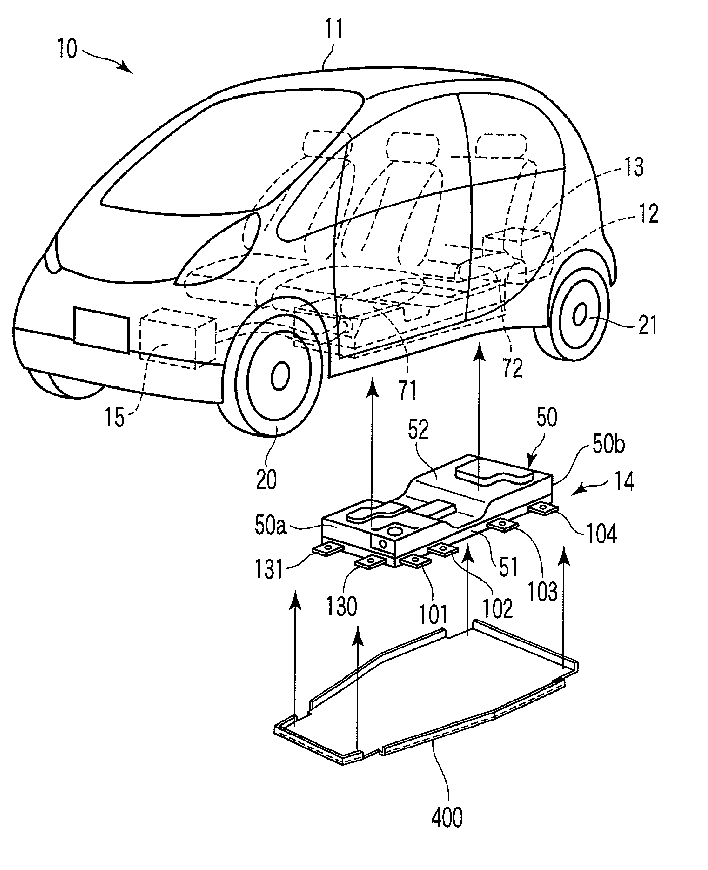
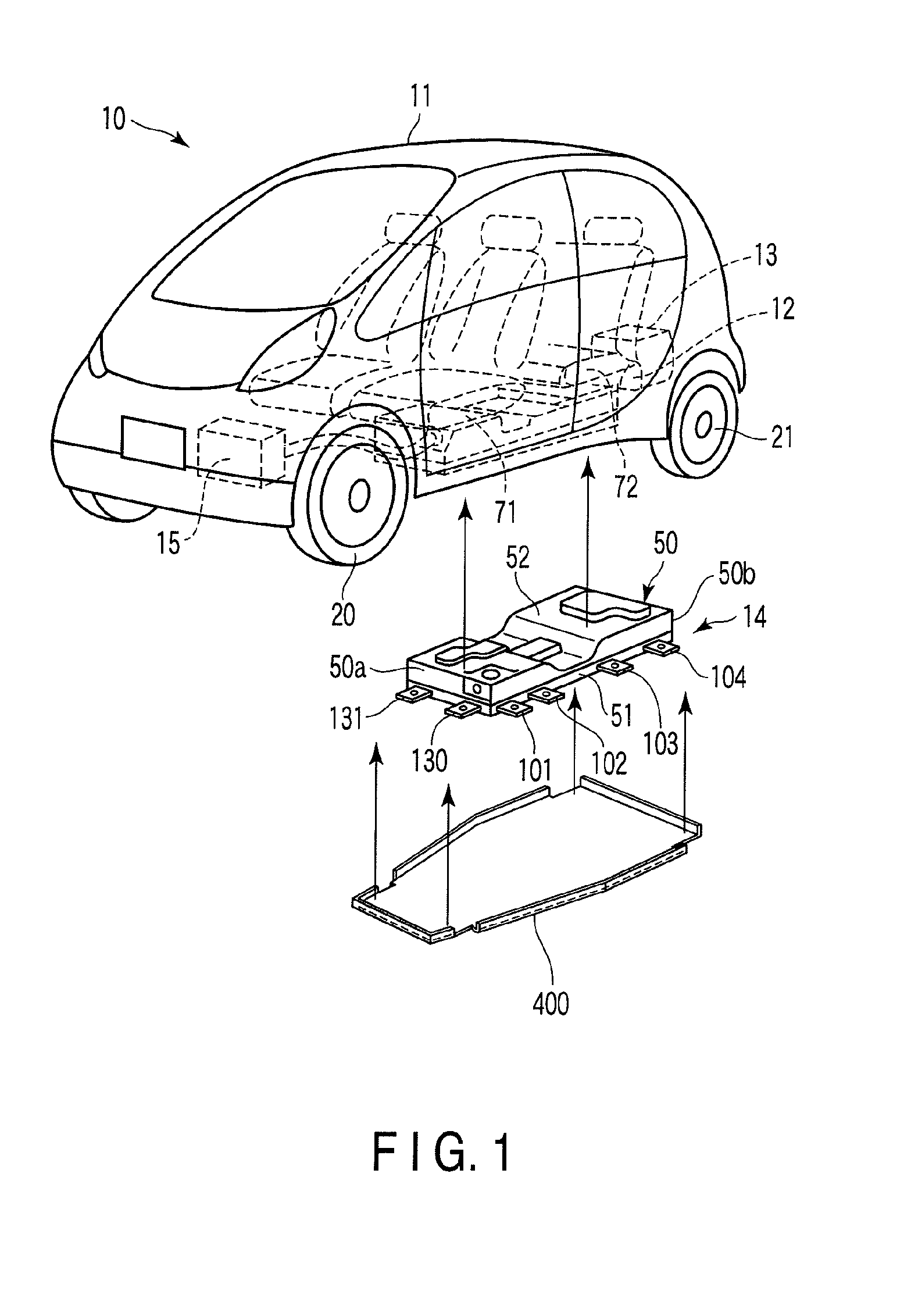
[0035]FIG. 1 shows an example of an electric vehicle 10. This electric vehicle 10 is provided with a motor 12 for traveling, and charging equipment 13 which are arranged at the rear part of the vehicle body 11, a battery unit 14 arranged under the floor of the vehicle body 11, and the like. A heat exchanger unit 15 for air-conditioning is arranged at the front part of the vehicle body 11.

[0036]The front wheels 20 of the vehicle 10 are supported by the vehicle body 11 by means of front suspensions (not shown). The rear wheels 21 are supported by the vehicle body 11 by means of rear suspensions (not shown). An example of the rear suspension is a trailing arm type rear suspension.

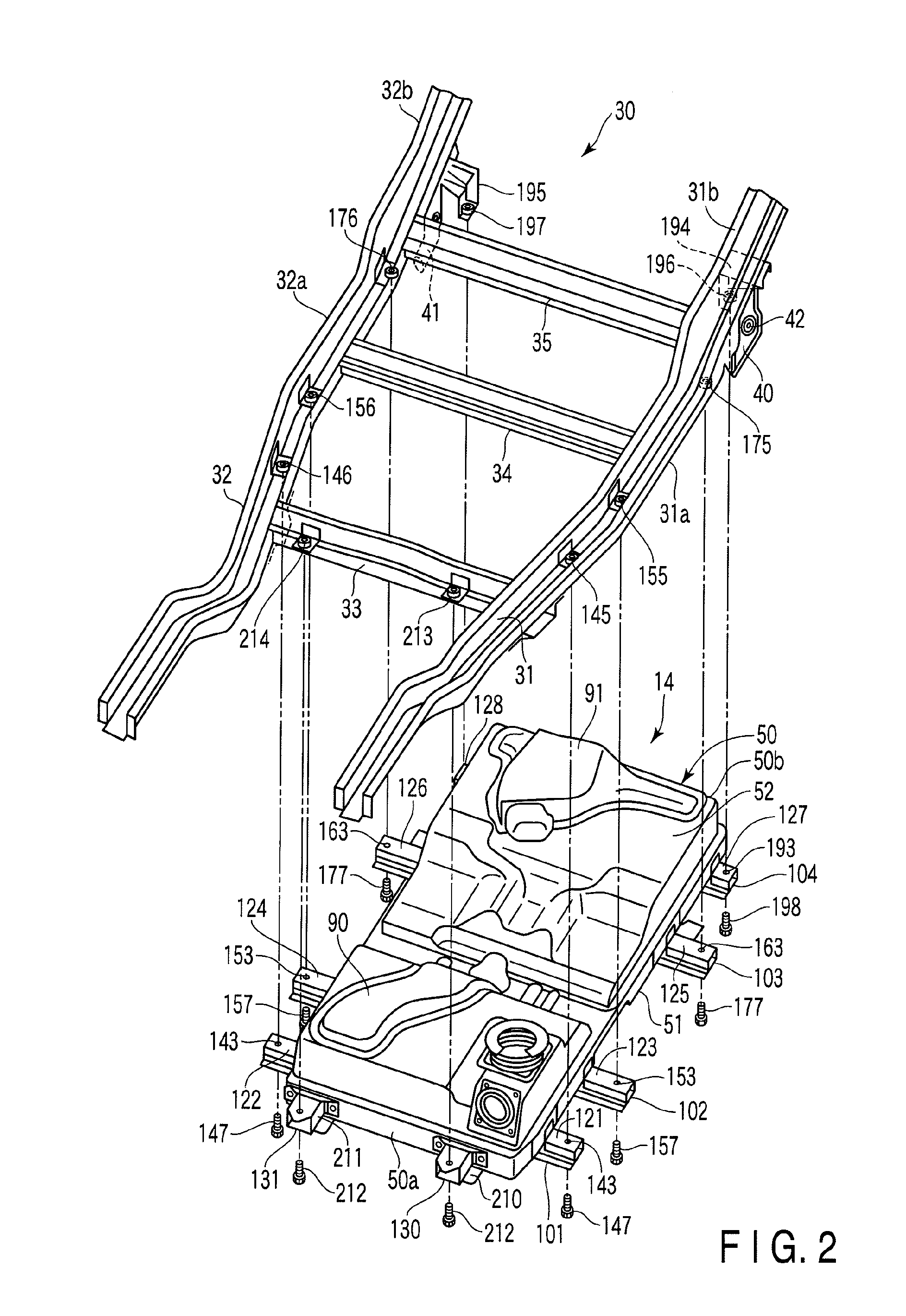
[0037]FIG. 2 shows a frame structure 30 constituting a lower skeletal structure of the vehicle body 11, and the battery unit 14 to be attached to the frame structure 30.

[0038]The frame structure 30 includes a p...


PUM

PropertyMeasurementUnit
widthaaaaaaaaaa
waterproof propertyaaaaaaaaaa
fluidityaaaaaaaaaa

Abstract

A battery case for containing therein battery modules includes a tray member, cover member, and seal member. The seal member is applied to a joint part between the tray member and cover member. Insert members made of metal are embedded in the resin of the tray member. Each of the insert members is provided with an embedded bolt a threaded part of which protrudes upward, and embedded nuts. The battery case is provided with first fastening sections and second fastening sections. In the first fastening section, a nut member is screwed onto the embedded bolt from above the cover member. In the second fastening section, a bolt member is screwed into the embedded nut from above the cover members.

Description

CROSS-REFERENCE TO RELATED APPLICATIONS[0001]This is a Continuation application of PCT Application No. PCT / JP2008 / 053996, filed Mar. 5, 2008, which was published under PCT Article 21(2) in Japanese.[0002]This application is based upon and claims the benefit of priority from prior Japanese Patent Application No. 2007-254263, filed Sep. 28, 2007, the entire contents of which are incorporated herein by reference.BACKGROUND OF THE INVENTION[0003]1. Field of the Invention[0004]The present invention relates to a battery case for containing battery modules of an electric vehicle which runs by means of a motor using a battery as a power source.[0005]2. Description of the Related Art[0006]A battery unit used for an electric vehicle includes battery modules and a battery case for containing the battery modules. An example of the battery case includes a tray member for supporting the battery modules, and a cover member for covering an upper part of the tray member.[0007]In, for example, Jpn. P...

Claims


Application Information

Patent Timeline
Patent Type & Authority Applications(United States)
IPC IPC(8): B60R16/04H01M50/204H01M50/227H01M50/244H01M50/249H01M50/262
CPCB60K1/04B60K2001/0438H01M2/1083B60R16/04H01M2/1072B60K2001/0472Y02E60/10H01M50/204H01M50/249B60L50/64H01M50/227H01M50/244H01M50/262Y02T10/70
Inventor TAKASAKI, SEIICHIIBUKI, TAKESHINISHINO, HARUCHIKA
Owner MITSUBISHI MOTORS CORP
Why Eureka
Try Eureka