Handle for Baking Device

a baking device and handle technology, applied in baking vessels, baking utensils, sealing, etc., can solve the problems of high production cost, complicated structure, and shake of baking utensils, and achieve the effect of reducing drilling work, convenient washing, and improving the appearance of the handl

Inactive Publication Date: 2009-09-24
TSANN KUEN CHINA ENTERPRISE
View PDF9 Cites 7 Cited by
  • Summary
  • Abstract
  • Description
  • Claims
  • Application Information

AI Technical Summary

Benefits of technology

[0009]Further, an inner cover board is installed under the main body of bakeware handle to cover the inward hollow; the upper surface of the inner cover board has two raised parts that extend upwards; each raised part is corresponding with each raised part that extend downwards of the inward hollow of the main body of bakeware handle. There are semicircle grooves at the opposite sides of the two raised parts of the inner cover plate and the two raised parts of the main body of bakeware handle to form pin jointed holes of the two ends of the short shaft of the raised ear. Increasing an inner cover board can improve the appearance of the handle and is convenient for washing. There are semicircle grooves at their opposite sides of the two raised parts of the inner cover plate and the two raised parts of the main body of bakeware handle, and the semicircle grooves form pin jointed holes for the two ends of the short shaft of the raised ear of the bakeware, which can be once-formed by pressure injection-mould and reduce a working procedure of drilling.
[0010]Further, each raised part of the inner cover board has a through hole, and each raised part of the main body of bakeware handle has a bolt hole corresponding with above through hole at the outer side of the semicircle grooves; the two bolts drill through the two through holes of the inner cover board to get into the two bolt holes of the main body of bakeware handle. The structure is also once formed by pressure injection-mould. The inner cover board is fixed to the main body of bakeware handle, which assembled easily.
[0011]The main body of the present bakeware handle whose tongue part extending to the bakeware is pin jointed with the short shaft of the raised ear of the side of the bakeware; the torsional spring covering the short shaft is set against the raised part and the main body of bakeware handle. The main body of bakeware handle has two position state relative to the short shaft of the raised ear, and its tongue part locks or gets separated from the shell of the electrical baking device, to come true its function of handle and locking hook. The main body of bakeware handle locks and gets separated from the shell of the electrical baking device just by a turning movement, which is simple and very fit for singlehanded action. The main body of bakeware handle and the inner cover board can be once formed by pressure injection-mould. The bakeware handle of the present invention has a simple structure, is machininged easily, can reduce the production cost greatly. There are semicircle grooves at their opposite sides of the two raised parts of the inner cover plate and the two raised parts of the main body of bakeware handle, and the semicircle grooves form pin jointed holes for the two ends of the short shaft of the raised ear of the bakeware. At the same time of fixing the inner cover board on the main body of bakeware handle by bolts, the main body of bakeware handle is pin jointed with the short shaft of the raised part, which is assembled easily and rapidly.

Problems solved by technology

If the bakeware can not be fixed on the heat-conducting plate, the bakeware will shake to affect its working even the bakeware is laid on the heat-conducting plate of the shell.
Above structure can overcome the problem of the connecting of the bakeware and the heat-conducting plate, but it also has disadvantageous as follows: there are oriented and position group of locking hook at the handle, which has a complicated structure, has a high production cost.

Method used


Image

  • Handle for Baking Device
  • Handle for Baking Device
  • Handle for Baking Device

Examples


Embodiment Construction

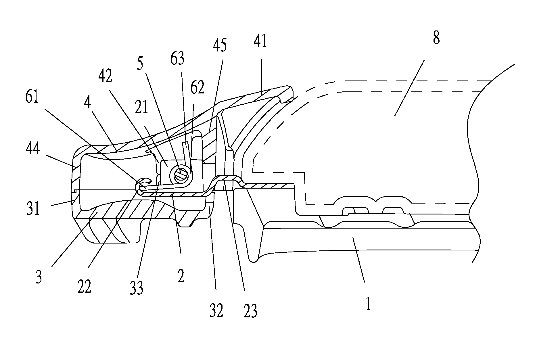
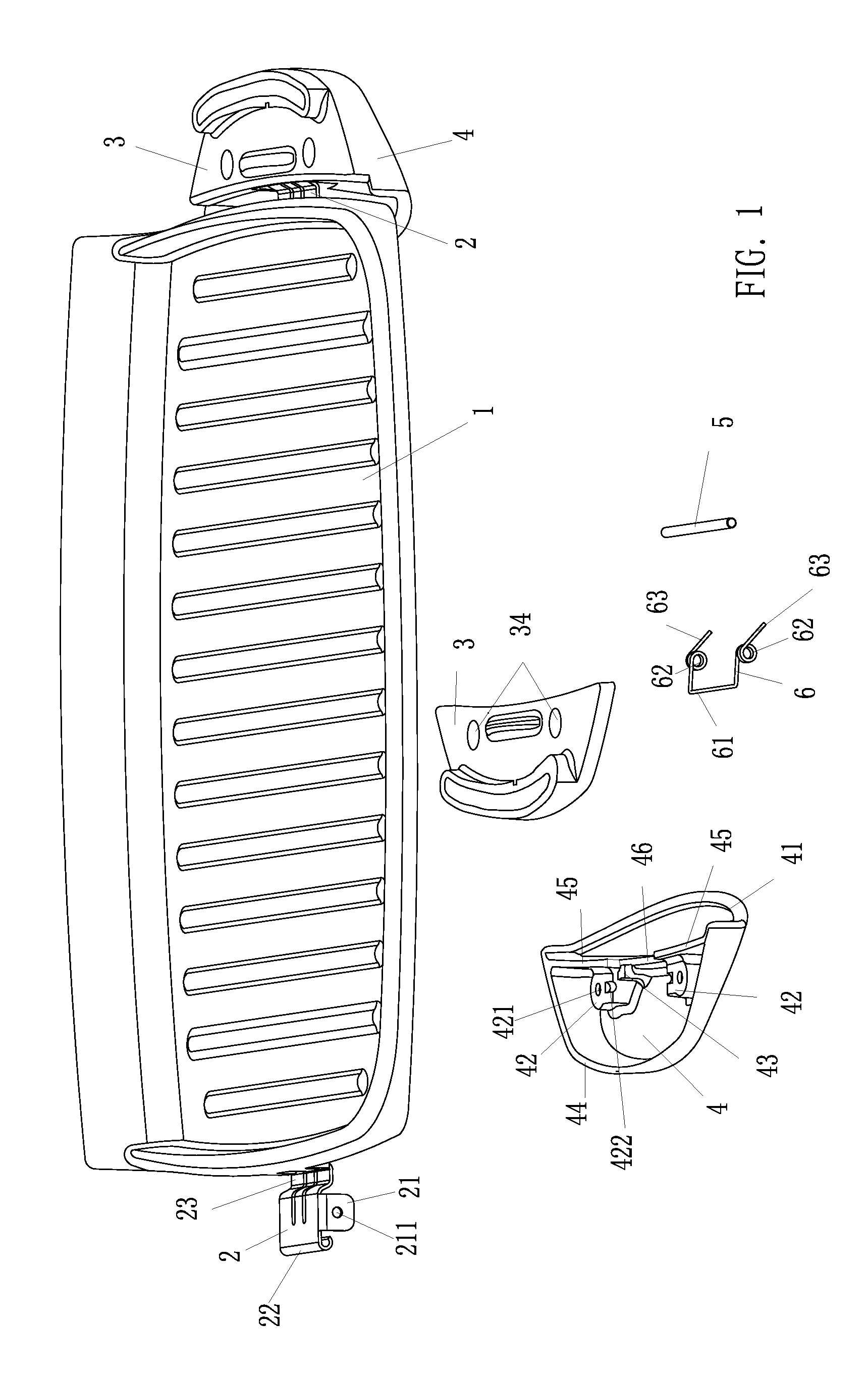
[0016]FIG. 1 is the structure of a bakeware 1 that adopts the bakeware handle of the present invention, and the bakeware 1 is set on the upside of double-faced electrical baking device with an upper shell. The bakeware is approximately rectangular and is founded by aluminum alloy. The nether surface (the surface with arris in FIG. 1) of the bakeware 1 is a baking side, and the upper surface of the bakeware 1 is a plane that is connected to the heat-conduction plate disposed on the upper shell of the electrical baking device. The left side and the right side of the bakeware 1 respectively have bakeware handles that are convenient for holding and moving the bakeware 1, and the bakeware 1 can be locked on the upper shell of the electrical baking device.

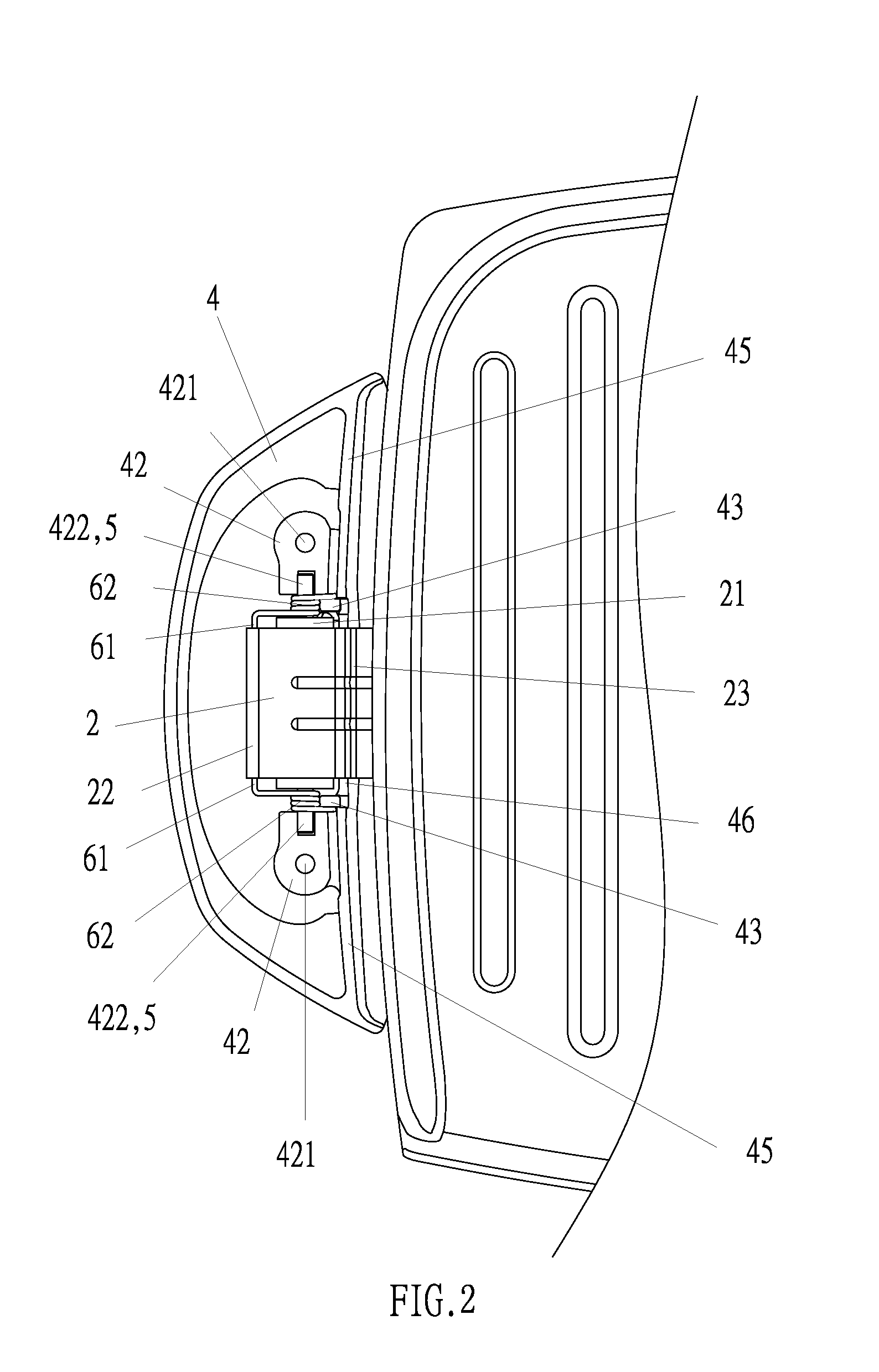
[0017]In the expanding structure of the left bakeware handle of the bakeware 1 in FIG. 1, the bakeware handle is composed of a raised ear 2, an inner cover board 3, a main body 4 of bakeware handle, a short shaft 5 and a torsional spring...


PUM


Abstract

A bakeware handle comprises a raised part fixedly connected to one side of the bakeware and extending outwards, and the raised ear has a short shaft; a main body of bakeware handle whose tongue part extends to the bakeware being pin jointed with the short shaft; at least a torsional spring covering the short shaft; one end of the torsional spring is set against the raised ear and the other end of the torsional spring is set against the main body of bakeware handle. In the immovable state of the main body of bakeware handle, the tongue part of the main body of bakeware handle is locked at the same edge of the shell that disposed on the bakeware of the electrical baking device. The bakeware is locked at the shell by the pretightening force of the torsional spring. When the main body of bakeware handle is turned relative to the short shaft, the torsional spring is compressed, and the tongue part of the main body of bakeware handle gets separated from the same edge of the shell that disposed on the bakeware of the electrical baking device, and the bakeware is taken away form the shell of the electrical baking device.

Description

CROSS REFERENCES TO RELATED APPLICATIONS[0001]This application claims priority to People's Republic of China Patent Application No.: 200820101727.9, filed on Mar. 18, 2008, the entire disclosure of which is incorporated herein by reference.FIELD OF THE INVENTION[0002]The present invention relates to an electrical baking device.RELATED ART[0003]In known electrical baking device, a metal reflecting board is set at the open end side of the insulating shell, an open window is provided in the middle of the reflecting board, a metal heat-conduction plate is provided in the window, wherein the heat-conduction plate, the reflecting board and the shell together form a closed room, and an electrical heating tube is fixedly connected to the heat-conduction plate.[0004]There is bakeware on the outer surface of the heating-conduction plate separately. The upper surface of the bakeware is baking side. In washing the bakeware, the bakeware is taken away from the heating-conducting plate of the she...

Claims


Application Information

Patent Timeline
Patent Type & Authority Applications(United States)
IPC IPC(8): A47J45/06
CPCA47J37/0676A47J36/10A47J45/061
Inventor XIE, LIFENGFU, XINBIAO
Owner TSANN KUEN CHINA ENTERPRISE
Why Eureka
Try Eureka