LED light source and method for adjusting chromaticity of LED light source

a technology of led light source and chromaticity adjustment, which is applied in the direction of discharge tube luminescnet screens, spark plugs, lighting and heating apparatus, etc., can solve the problems of difficult to fix or fix the reflective frame, and difficult to increase or decrease the amount of transparent resin, etc., to achieve the effect of easy adjustment of chromaticity and easy to achieve chromaticity adjustmen

Active Publication Date: 2009-09-24
CITIZEN WATCH CO LTD
View PDF0 Cites 21 Cited by
  • Summary
  • Abstract
  • Description
  • Claims
  • Application Information

AI Technical Summary

Benefits of technology

[0022]According to the present invention, by forming the ink coating layer, it is possible to provide an LED light source that can easily adjusts its chromaticity without having to virtually change its outer shape and without suffering much damage during the chromaticity adjustment process.
[0023]Furthermore, according to the present invention, by forming the ink coating layer, it is possible to provide an LED light source that can easily accomplish the chromaticity adjustment so that the color temperature of the emergent light becomes substantially uniform regardless of the angle of emergence.

Problems solved by technology

Generally, an LED light source constructed by combining an LED device with a resin containing a phosphor that absorbs a portion of the light emitted from the LED device and emits light at a different wavelength has had the problem that the chromaticity of the LED light source varies due to such factors as variations in the wavelength of the LED device itself and variations in phosphor content.
However, in applications that impose limitations on the external shape of the LED light source, it has been difficult to increase or decrease the amount of the transparent resin.
Furthermore, when grinding is performed, the LED light source may be damaged due to the applied force or scratches, leading to problems such as a break in the wire bonding or scratches on the reflective frame.
That is, the prior art has had the problem that the light from the LED device, when viewed straight on, for example, appears bluish, but as the viewing angle is changed, the light appears yellowish.

Method used


Image

  • LED light source and method for adjusting chromaticity of LED light source
  • LED light source and method for adjusting chromaticity of LED light source
  • LED light source and method for adjusting chromaticity of LED light source

Examples


Embodiment Construction

[0041]An LED light source and a chromaticity adjustment method for an LED light source according to the present invention will be described below with reference to the drawings. It should, however, be noted that the technical scope of the present invention is not limited to the specific embodiments described herein, but extends to the inventions described in the appended claims and their equivalents.

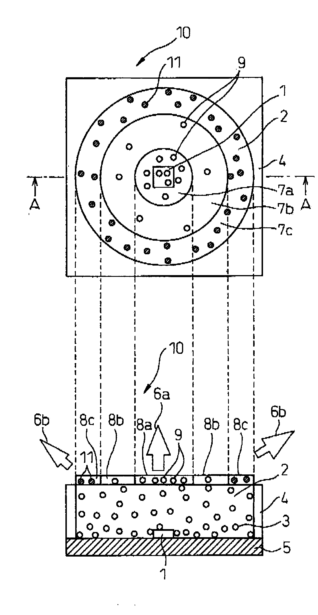
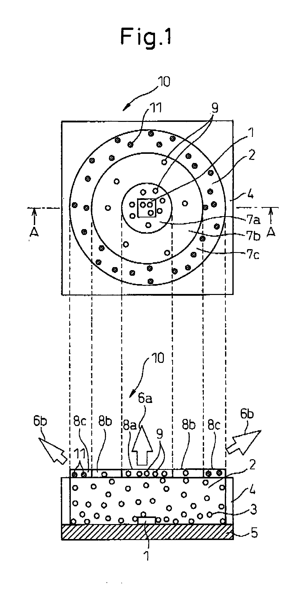
[0042]FIG. 1 is a diagram showing, by way of example, a top view and a cross-sectional view of an LED light source 10 according to the present invention. The cross-sectional view shown at the bottom is a view taken along line AA′ in the view shown thereabove (the top view of the LED light source 10).

[0043]In the LED light source 10, an LED device 1 is die-bonded to electrodes (not shown) formed on a substrate 5, and the anode and cathode of the LED device 1 are tied to the electrodes by wires. A transparent resin 2 with phosphors 3 uniformly mixed therein is embedded inside a package fra...


PUM


Abstract

The present invention is directed to the provision of an LED light source that can easily adjust its chromaticity and a chromaticity adjustment method for such an LED light source. More specifically, the invention provides a chromaticity adjustment method for an LED light source having an LED device, a phosphor which absorbs a portion of light emitted from the LED device and emits light by wavelength conversion, and a resin material containing the phosphor and disposed so as to enclose the LED device, wherein an ink coating layer is disposed on a surface of the resin material in order to adjust chromaticity; the invention also provides an LED light source adjusted in such a manner.

Description

[0001]This application claims priority of Japanese Application No. 2008-075642, filed Mar. 24, 2008, the content of the Japanese Application No. 2008-075642 is incorporated herein by reference.FIELD OF THE INVENTION[0002]The present invention relates to an LED light source and a chromaticity adjustment method for an LED light source, and more particularly to a chromaticity adjustment method for an LED light source that adjusts the chromaticity by using an ink coating layer.BACKGROUND OF THE INVENTION[0003]Generally, an LED light source constructed by combining an LED device with a resin containing a phosphor that absorbs a portion of the light emitted from the LED device and emits light at a different wavelength has had the problem that the chromaticity of the LED light source varies due to such factors as variations in the wavelength of the LED device itself and variations in phosphor content.[0004]In view of this, an attempt has been made to suppress the variation of the chromatic...

Claims


Application Information

Patent Timeline
Patent Type & Authority Applications(United States)
IPC IPC(8): H01J1/62H01J9/42H01L33/32H01L33/48H01L33/50H01L33/56H01L33/62
CPCH01L33/44H01L33/50H05B33/22H01L2224/48091H01L2224/8592H01L2924/3025H01L2924/00014H01L2924/00H01L2924/181H01L2924/00012
Inventor YOKOYAMA, MASAFUMISAKAI, KEISUKE
Owner CITIZEN WATCH CO LTD
Why Eureka
Try Eureka