Radio frequency identification asset management system and method

a technology of asset management system and radio frequency identification, applied in the field of radio frequency identification asset management system and method, can solve the problems of increasing the likelihood of a container being misplaced, few options available to track and manage assets, and few tools that allow hospitals to accurately track, maintain and properly distribute medical and other mobile equipmen

Inactive Publication Date: 2009-09-24
TRENSTAR
View PDF85 Cites 54 Cited by
  • Summary
  • Abstract
  • Description
  • Claims
  • Application Information

AI Technical Summary

Benefits of technology

[0015]The present invention addresses and resolves the above-identified, as well as other limitations, with conventional RFID asset tracking systems. The present invention provides a comprehensive asset tracking software infrastructure, and RFID hardware technology for asset tracking. The present invention includes a software-based asset management system and hardware solution that enables users to effectively support efficient distribution of assets, such as medical assets or shipping crates.
[0016]One aspect of the present invention provides a zonal approach to the tracking of RFID assets. By using RFID hardware, related software, and specialized antennas in a unique way, the system provides an RFID resolution that is more accurate than conventional approaches, while providing the broadest RFID coverage within a hospital setting. The system uses improved RFID tag readers, which allow for a customized antenna pattern, thus improving the resolution needed to accurately track the location of assets.
[0017]The system also utilizes a “cube” design for an RFID tag, which reduces the physical footprint of the tag, as compared to conventional active RFID tagging systems. This RFID tag also exhibits improved RF capabilities over the conventional devices by emitting a consistent antenna pattern around the circumference of the RFID tag. This approach reduces the “dead spots” in the RF field surrounding the tag, and allows the RFID tag to be detected similarly, regardless of its orientation. Other tag designs may be utilized, with that also emit a consistent antenna pattern.
[0018]The improved performance of the RFID reader and tag allows a hospital facility to be segmented into zones corresponding to logical and physical separations within the facility. These zones can be relatively small areas, such as a utility closet, or large areas such as a facility lobby. Each of these areas is set up using an RFID reader which has both an antenna to communicate with the RFID tags and an antenna to communicate with a wireless fidelity Wi-Fi access point. The antenna used to communicate with the RFID tags can be shaped in various configurations to appropriately cover a specified area, thus allowing for the various zones to be created. The RFID reader uses the Wi-Fi antenna to communicate with the Wi-Fi access point. The Wi-Fi access point is then configured to be connected to the hospital network allowing for the asset tracking software to manage the mobile RFID assets. The RFID tag reader is also able to be optionally connected to the hospital network via an alternative network connection. For example an Ethernet connection (FDDI, Firewire) or any other similar connection may be used to allow for the RFID tag reader to communicate to the hospital network.
[0021]The software-based asset management system provides users with the ability to track the states of assets including available for use, in use, soiled or out of use, or out of service. Users of the system are also able to track all movements within a facility between facilities of particular assets, and also assess whether assets are moving or not moving. Multi-attribute searches can be performed in order to find a specific asset. The software is also a web-based, hosted, tracking solution for asset tracking needs. The software has also been written to be accessible via a PDA device. This is a unique advantage of the system because it combines true mobility for support workers in managing mobile devices. No other RFID-enabled asset tracking solution provides handheld functionality.
[0022]Complicated equipment requisition, distribution, and fulfillment tasks related to the various assets can also be performed by the present invention. Some of the capabilities of the system that assist in this functionality include integrated requisition work flow functionality including ad-hoc equipment requisition, standing orders for equipment, and tracking of equipment requests. Also, proactive equipment replenishment and staging based on demand can be automated so that various assets may be reordered or relocated. Various other advantages provided by the software system will become apparent in the following detailed description of the invention. The present invention also presents a unique business process that is enabled and supported by the abovementioned hardware and software attributes. The functionality of the system streamlines and automates several equipment management business processes. The system allows for the development of a business model that ensures compliance with regulatory procedures, automatically identifies equipment requirements, streamlines equipment requisition and workflow, and minimizes manual search activity.

Problems solved by technology

However, currently there are few tools available that allow hospitals to accurately track, maintain and properly distribute medical, and other mobile equipment (e.g., beds, wheelchairs, carts, laptop computers, etc.).
Hospitals spend large amounts of funds on various medical supplies and apparatuses, but have few options available to track and manage their assets and ensure that their resources are being used as efficiently as possible.
Similar issues exist in other environments where the business relies on ready-use of mobile assets.
For instance in a warehouse environment, various containers are often moved from one location to the next, with some uncertainty arising regarding a present location of a specific container at any given time.
As more employees move containers from one location to another, or move groups of containers so as to access a specific container, the likelihood of a container being misplaced increases.
It is impractical to place large wire antennas within small tags; accordingly, comparatively small magnetic loop antennas are the coupling methods of choice for such small tags.
These magnetic loop antennas exhibit a serious drawback, however, in that they have characteristic “figure-8” sensitivity pattern and, in certain positions and / or orientations, can reject or otherwise not detect the fields generated from the sensor.
When such rejection occurs, the tag may be well within the sensor's intended field, but fails to detect the tag's emissions, and therefore also fails to communicate therewith.
A related problem is when the position and / or orientation of the reader within the field is varied, thereby taking the readers out of the “figure-8” pattern of the tag antenna, and interrupting communication between the reader and tag.
Additionally, many existing RFID tag / reader systems do not have the ability to locate the tag in 3-dimensional space.
These systems fail to have the precision needed to detect that an RFID tag is on a specific floor, or that the tag is located in a specific room if readers are located in two adjacent rooms.
In a system with poor tracking fidelity, tracking the assets using software proves to be difficult because the exact location of the tag can not be determined to the precision required by the tacking software.
Conventional systems have also implemented infrared IR detection systems to perform asset tracking functions, however the present inventors recognized a drawback to implementing such a system is that the reader and the IR tag must be in visual range of one another for the tag to be properly read.
Thus, assets can be easily moved without being detected by the IR tag reader, making accurate asset tracking difficult.
Additionally, the conventional systems described above include RFID tags of various elongated shapes, which are not always compatible with the various assets that are to be tracked.
Specifically, difficulties are encountered with large RFID tags are to be attached to small devices and therefore make using the small device awkward and cumbersome.
Also, as discussed above, the various tag designs cause the RF field emitted from the tag to be non-uniform and thus dependent upon the orientation of the tag for detection.
Furthermore, such conventional systems fail to be supported by sufficient software systems that manage, track and allow maintenance of the assets including the RFID tags.
The conventional systems allow the assets to be tracked; however they do not provide specialized functionality for the hospital environment.

Method used


Image

  • Radio frequency identification asset management system and method
  • Radio frequency identification asset management system and method
  • Radio frequency identification asset management system and method

Examples


Embodiment Construction

[0040]The following comments relate to the drawings, wherein like reference numerals designate identical or corresponding parts throughout the several views.

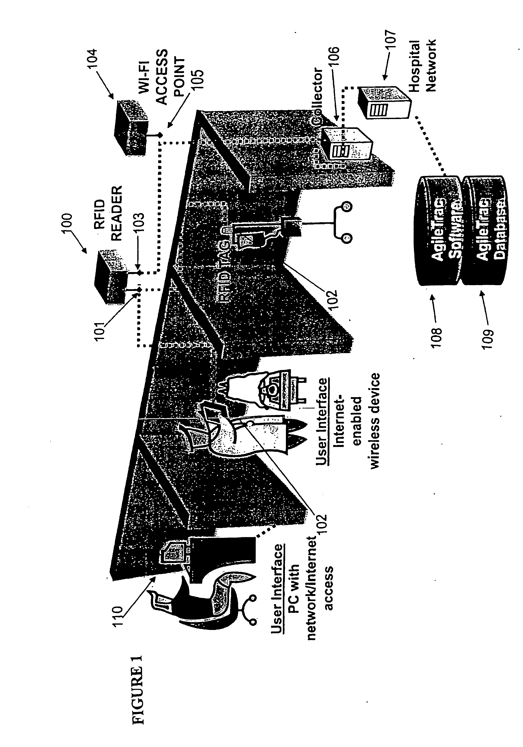
[0041]FIG. 1 illustrates an overview of hardware that may be used to implement the RFID tracking system according to the present invention. The system includes an RFID reader 100 including an antenna device 101 for communicating with RFID tags (or simply “tag”) 102 and internet enabled wireless devices 111, and an antenna device 103 for communicating with a Wi-Fi access point 104. The antenna on the Wi-Fi access point 105 transmits information obtained from the RFID reader 100 to a collector 106, which forwards the collected information onto the hospital network 107. Once the information is forwarded to the hospital network 107, the system software 108 in conjunction with the system database 109, can be used to manage the assets of the system. A personal computer (PC) 110 may also be provided which has access to the hospital net...


PUM


Abstract

A radio frequency identification (RFID) tracking system to track and manage assets. Each asset to be tracked is tagged with an RFID tag, and tracked using RFID readers located throughout a facility. Based on the tracking information, the system allows users to manage assets and generate reports regarding the various tagged assets.

Description

CROSS REFERENCE TO RELATED APPLICATION[0001]This application is a continuation of and claims priority to U.S. Ser. No. 11 / 121,978, filed May 5, 2005, which claims priority to copending U.S. provisional application entitled, “Asset Management System, Apparatus, Method and Computer Program Product,” having Ser. No. 60 / 567,770, filed May 5, 2004, which is entirely incorporated herein by reference.BACKGROUND OF THE INVENTION[0002]1. Field of the Invention[0003]This invention relates to systems, apparatuses, methods, and computer program products relating to tracking and managing assets, such as medical assets, beverage containers, and manufacturing inventory. More particularly, the invention relates to using radio frequency identification (RFID) tags to track, manage, and maintain mobile and / or portable assets in a medical facility, shipping facility, inventory warehouse, or other similarly configured facility that houses mobile assets.[0004]2. Discussion of the Background[0005]In today...

Claims


Application Information

Patent Timeline
Patent Type & Authority Applications(United States)
IPC IPC(8): G08B13/14G06F17/30G06Q10/00H04B1/00H04B1/04
CPCG06Q10/06H04B1/04G06Q10/087
Inventor NEUWIRTH, DANIEL
Owner TRENSTAR
Why Eureka
Try Eureka