Display device and method for luminance adjustment of display device

a display device and luminance adjustment technology, applied in the field of display devices and luminance adjustment methods of display devices, can solve the problems of affecting the appearance of the display screen, reducing the size of the aperture, and hindering the incidence of ambient light on the ambient light sensor b>9/b>, so as to achieve simplified mounting process, improved accuracy, and convenient manufacturing of display devices

Active Publication Date: 2009-09-24
JAPAN DISPLAY INC
View PDF4 Cites 35 Cited by
  • Summary
  • Abstract
  • Description
  • Claims
  • Application Information

AI Technical Summary

Benefits of technology

[0024]According to the configurations of the first and second embodiments of the present invention, the ambient light sensor provided in the effective pixel area allows outputting of the result of detection of the ambient light amount for luminance adjustment while effectively avoiding the situation in which the incidence of ambient light on the ambient light sensor is hindered, arising due to a case and so on when the ambient light sensor is provided outside the effective pixel area. Therefore, according to the configurations of the first and second embodiments of the present invention, a display device can be fabricated more easily through a simplified mounting process therefor compared with the related arts, and the luminance adjustment can be carried out with higher accuracy. Furthermore, the hue correction mechanism in the configurations of the first and second embodiments of the present invention can prevent local hue change due to the lowering of the aperture area

Problems solved by technology

Furthermore, the black frame having a large width impairs the appearance of the display screen.
However, the display device 31 inevitably involves the occurrence of an error in the mounting of the liquid crystal display panel 1 or 21 to the case 32, and therefore decreasing the size of the aperture 32A will lead to the possibility that the incidence of ambient light on the ambien

Method used


Image

  • Display device and method for luminance adjustment of display device
  • Display device and method for luminance adjustment of display device
  • Display device and method for luminance adjustment of display device

Examples


first embodiment

(1) Configuration of First Embodiment

(1-1) Entire Configuration (FIGS. 2 to 6)

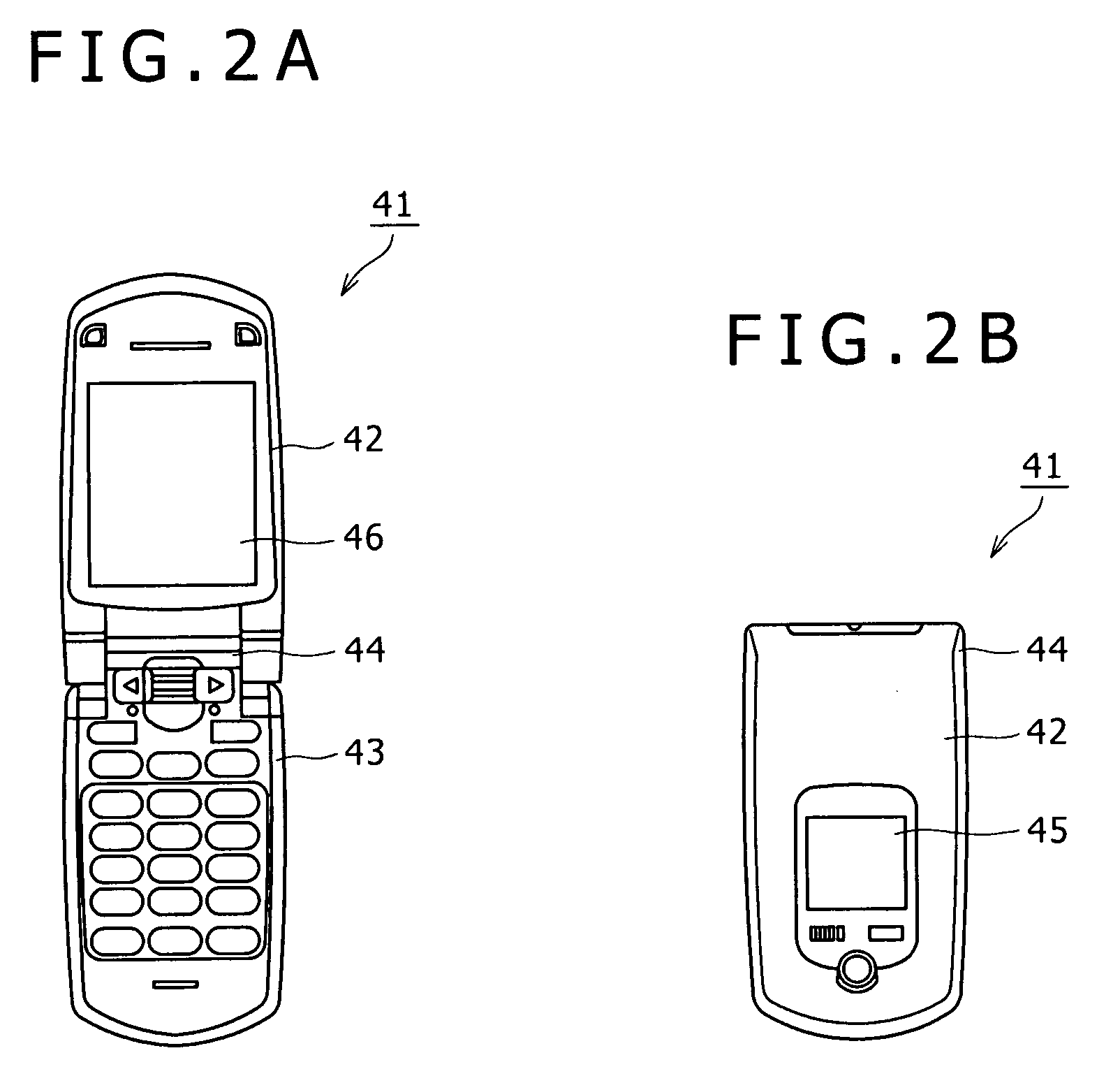
[0052]FIGS. 2A and 2B are plan views showing a cellular phone as a display device according to a first embodiment of the present invention. FIG. 2A shows a cellular phone 41 in the opened state, and FIG. 2B shows it in the folded state. This cellular phone 41 includes an upper case 42, a lower case 43, and a connection 44 that allows the upper case 42 to be foldably connected to the lower case 43. In this cellular phone 41, a sub-display part 45 is provided outside the upper case 42 so that a user can be informed of various kinds of information when the cellular phone 41 is in the folded state. Furthermore, in the cellular phone 41, a main display part 46 is provided inside the upper case 42 so that a user can be informed of various kinds of information when the cellular phone 41 is in the opened state. The configuration according to the embodiment of the present invention is applied to the main display pa...

second embodiment

[0082]In a liquid crystal display device according to a second embodiment of the present invention, the ambient light sensors are disposed in green sub-pixels PXG on the outermost periphery of the effective pixel area. If no ambient light sensor 9 is disposed as shown in FIG. 8A, the aperture ratios of all of the sub-pixels PXR, PXG, and PXB are set substantially the same. Therefore, e.g. in displaying of white on the entire screen, a uniform white screen can be obtained.

[0083]If the ambient light sensor 9 is disposed in the effective pixel area, a sense of discomfort due to the provision of the ambient light sensor 9 is smaller when the ambient light sensor 9 is disposed in peripheral part of the screen than when it is disposed in center part of the screen. Therefore, in this embodiment, as shown in FIG. 8B, the ambient light sensor 9 is disposed in each of the plural green sub-pixels PXG that are the closest to the sensor circuit and continuous along the vertical direction of the ...

third embodiment

[0086]In the configuration of the second embodiment, the aperture ratio is lowered in the pixels in which the ambient light sensors and the light blockers are provided and the luminance value is lowered in these pixels, although hue change due to the provision of the ambient light sensors can be prevented. As a result, in the configuration of the second embodiment, if a white frame image with a small width is displayed on the outermost periphery as shown in FIG. 9 for example, the lowering of the luminance value of the pixels having the ambient light sensors is perceived, which gives a sense of discomfort to the user.

[0087]To address this problem, a third embodiment of the present invention is configured as shown in FIG. 10 on the premise of the configuration of the second embodiment. Specifically, light blockers 80R, 80G, and 80B are provided in the red, green, and blue sub-pixels that are on the outermost periphery of the effective pixel area and to which the ambient light sensor ...


PUM


Abstract

Disclosed herein is a display device that displays a desired image on an effective pixel area in which sub-pixels are arranged in a matrix, the display device including: an ambient light sensor configured to be provided in a predetermined sub-pixel in the effective pixel area, the ambient light sensor receiving ambient light and outputting a result of detection of an ambient light amount for adjustment of luminance of the image; and a hue correction mechanism configured to correct local hue change due to provision of the ambient light sensor in the predetermined sub-pixel.

Description

CROSS REFERENCES TO RELATED APPLICATIONS[0001]The present invention contains subject matter related to Japanese Patent Application JP 2008-071400 filed in the Japan Patent Office on Mar. 19, 2008, the entire contents of which being incorporated herein by reference.BACKGROUND OF THE INVENTION[0002]1. Field of the Invention[0003]The present invention relates to a display device and a method for luminance adjustment of a display device, and can be applied to e.g. a liquid crystal display device. The present invention is to allow effective avoidance of image quality deterioration although an ambient light sensor for detection of the ambient light amount is provided in the effective pixel area, by correcting hue change due to an aperture ratio decrease accompanying the provision of the ambient light sensor by use of a hue correction mechanism.[0004]2. Description of the Related Art[0005]Among various kinds of display devices such as liquid crystal display devices, ones in which luminance...

Claims


Application Information

Patent Timeline
IPC IPC(8): G06F3/038G02F1/133G09G3/36
CPCG02F1/133514G02F1/1362G02F2201/58G09G3/3648G09G2360/148G09G2300/0465G09G2320/0242G09G2360/144G09G2300/0443H04N5/57H04N9/64
Inventor OTANI, NATSUKINAKANISHI, TAKAYUKI
Owner JAPAN DISPLAY INC
Why Eureka
Try Eureka