System and method for correlating and synchronizing a three-dimensional site model and two-dimensional imagery

a site model and two-dimensional imagery technology, applied in the field of computer graphics, can solve the problems of difficult to identify what a user is looking at when viewing images, the type of software imaging applications are difficult to manage and view in a spatially accurate context, and drawbacks of such commercially available systems, so as to achieve the effect of improving the imag

Inactive Publication Date: 2009-09-24
HARRIS CORP
View PDF13 Cites 65 Cited by
  • Summary
  • Abstract
  • Description
  • Claims
  • Application Information

AI Technical Summary

Benefits of technology

[0009]A dynamic heading indicator can be displayed and synchronized to a rotation of the three-dimensional site model image. The processor can update at least one of the 2D and 3D databases based upon additional information obtained while a user interacts with an image. The 2D database can be formed of rasterized vector data and the 3D database can include data for a local space rectangular or world geocentric coordinate systems. Both the 2D and 3D databases can store ancillary data to the 2D database and 3D database and provide additional data that enhances an image during user interaction with an image.

Problems solved by technology

There are some drawbacks to such commercially available systems, however.
Some software imaging applications display interior images that give detail without site reconstruction and are becoming more readily available, but even these type of software imaging applications are difficult to manage and view in a spatially accurate context.
A number of these applications do not have the imagery geospatially referenced to each other and it is difficult to identify what a user is looking at when viewing the images.
For example, it is difficult for the user to determine which room or rooms are contained in any given image, especially when there are many similar images that make it difficult for a user to correlate and synchronize between the various images, especially when the user pans or rotates an image view.
Some interior imaging systems, for example, those having power to display 360-degree panoramic images, can capture interior details It is difficult, however, even in these software applications, to comprehend what any given portion of an image references, for example, which room is displayed or which hallway is displayed within the image or which room is next to which room, and what is behind a given wall.
This becomes even more difficult when the rooms and hallways in a building look similar such that a user has no bearing or common reference to use for orientation relative to the different hallways and rooms within the building.
It is possible to label portions of the image with references so the user understands better what they are looking at, but this does not sufficiently solve this problem, which is further magnified when there are dozens of similar images.
Both images having no geospatial context, making it difficult to determine where the user is located relative to the different rooms, open spaces, and hallways when viewing the two different, but similar looking panoramic images 12, 14.
Simply querying or clicking-on a marker in a serial manner, however, does not give the user the context of this information concerning the location the user is referenced at that site.
Furthermore, it is difficult to comprehend the contents of an image that contains many rooms or unique perspectives.
Even with markers, these images still would not show how components within the image relate to each other.

Method used


Image

  • System and method for correlating and synchronizing a three-dimensional site model and two-dimensional imagery
  • System and method for correlating and synchronizing a three-dimensional site model and two-dimensional imagery
  • System and method for correlating and synchronizing a three-dimensional site model and two-dimensional imagery

Examples


Embodiment Construction

[0018]Different embodiments will now be described more fully hereinafter with reference to the accompanying drawings, in which preferred embodiments are shown. Many different forms can be set forth and described embodiments should not be construed as limited to the embodiments set forth herein. Rather, these embodiments are provided so that this disclosure will be thorough and complete, and will fully convey the scope to those skilled in the art. Like numbers refer to like elements throughout.

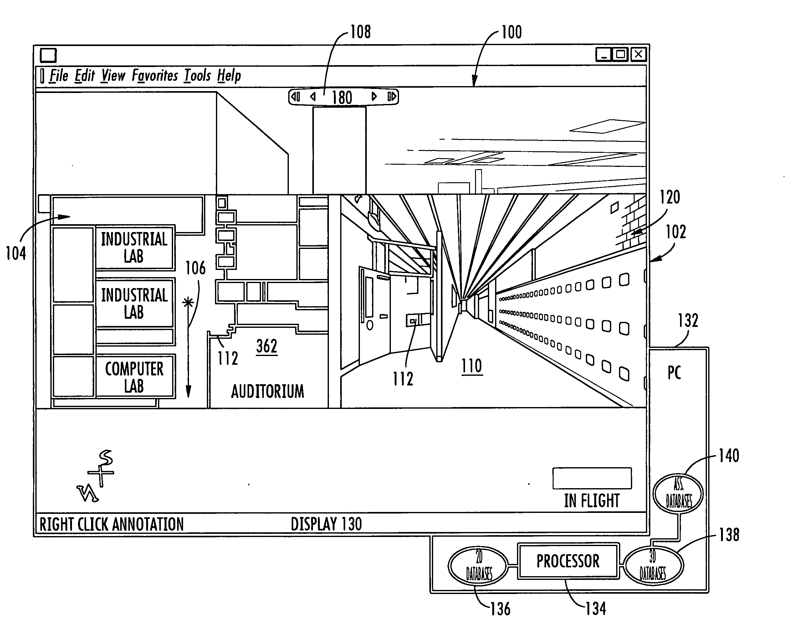
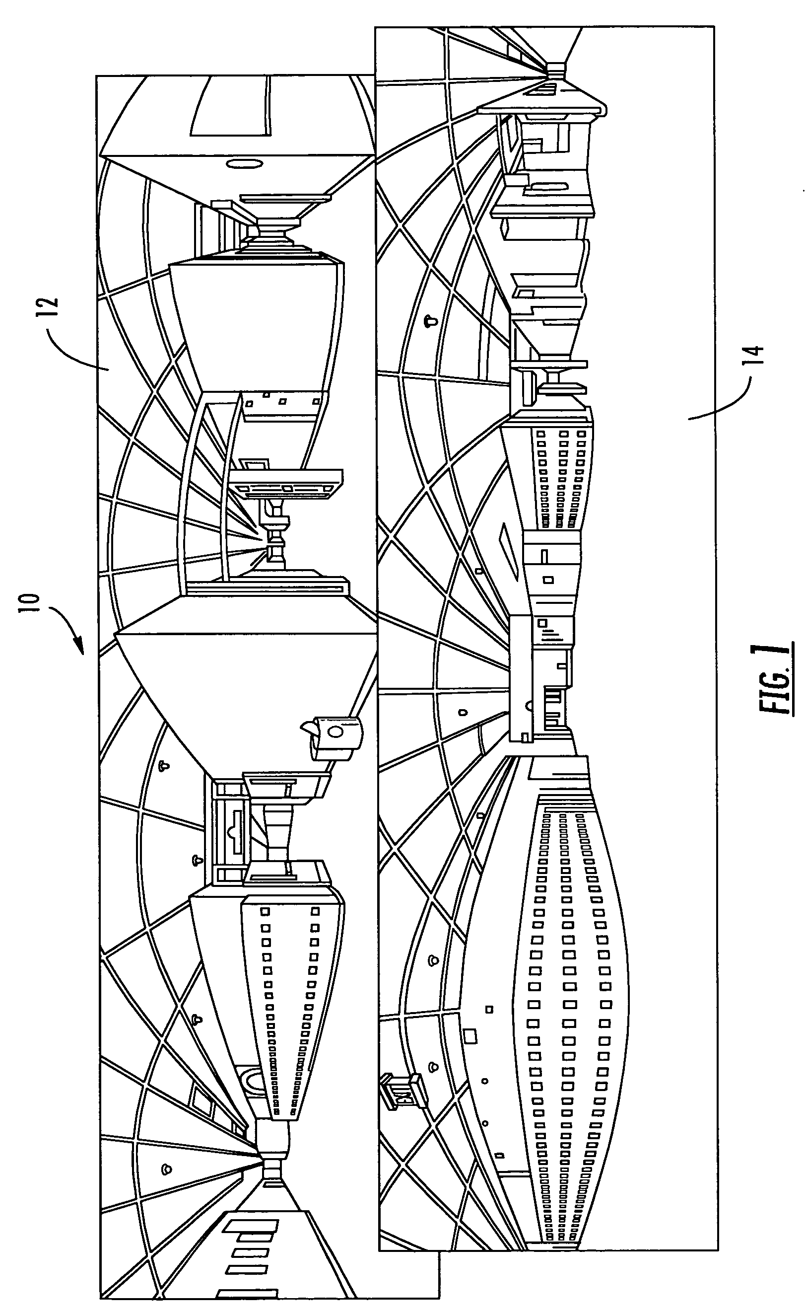
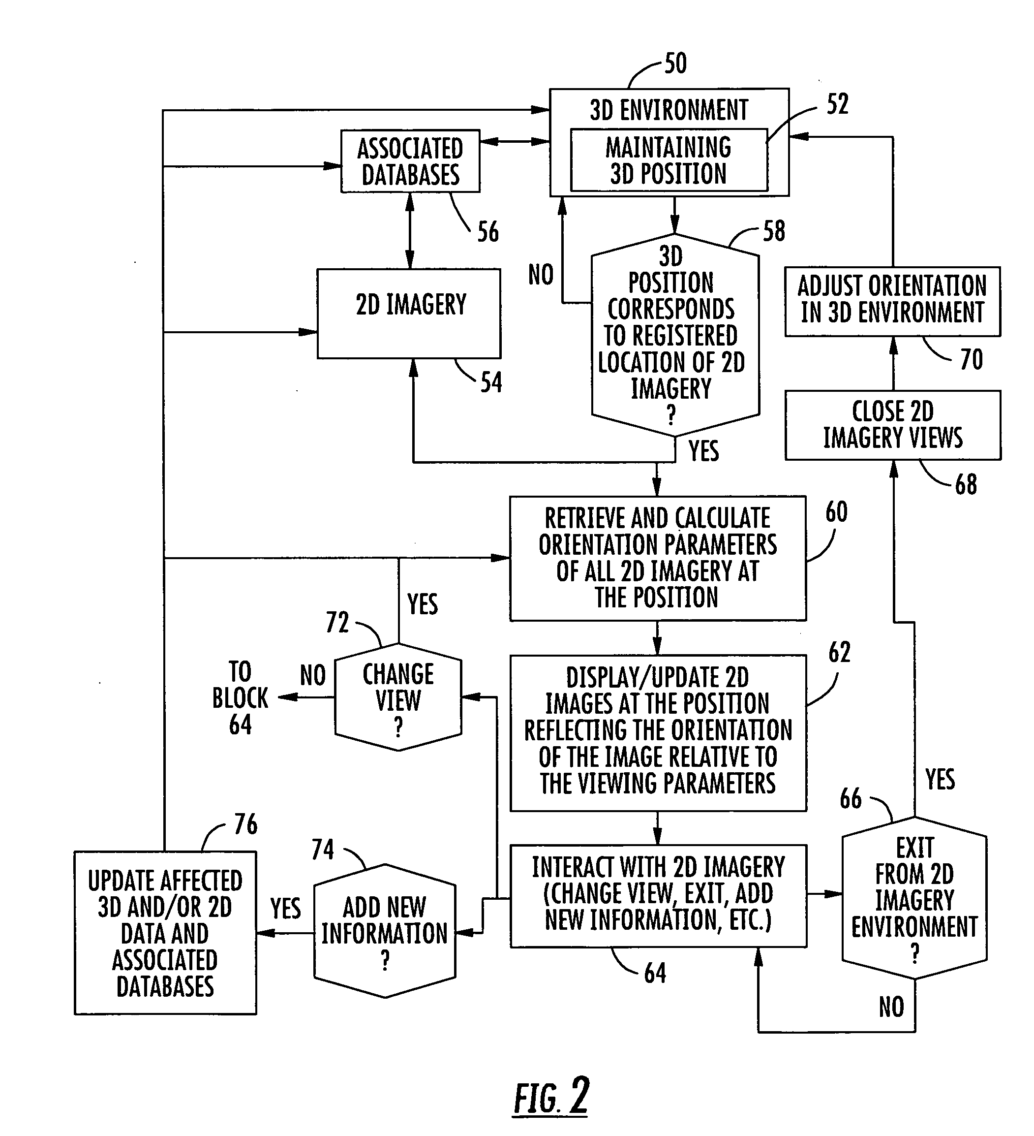
[0019]In accordance with a non-limiting example of the present invention, the system and method correlates and synchronizes a three-dimensional site model and two-dimensional imagery with real or derived positional metadata, for example, floor plans, panoramic images, video and similar images to establish and maintain a spatial orientation between the images, such as formed from disparate data sets. For example, a two-dimensional floor plan image could be displayed as centered on a collection p...


PUM


Abstract

An imaging system includes a 3D database for storing data relating to three-dimensional site model images having a vantage point position and orientation when displayed. A 2D database stores data relating to a two-dimensional image that corresponds to the vantage point position and orientation for the three-dimensional site model image. Both the three-dimensional site model image and two-dimensional imagery are displayed typically on a common display A processor operative with the two-dimensional and three-dimensional databases and will create and display the three-dimensional site model image and two-dimensional imagery from data retrieved from the 2D and 3D databases and correlates and synchronizes the three-dimensional site model image and two-dimensional imagery to establish and maintain a spatial orientation between the images as a user interacts with the system.

Description

FIELD OF THE INVENTION [0001]The present invention relates to the field of imaging and computer graphics, and more particularly, this invention relates to a system and method for correlating and synchronizing a three-dimensional site model and two-dimensional imagery.BACKGROUND OF THE INVENTION [0002]Some advanced imaging systems and commercially available software applications display two-dimensional imagery, for example, building interiors, floor plan layouts and similar two-dimensional images, and also display three-dimensional site model structures to provide spatial contextural information in an integrated environment. There are some drawbacks to such commercially available systems, however. For example, a majority of photogrametrically produced three-dimensional models have no interior details. A familiarization with building interiors while viewing a three-dimensional model would be useful to many users of such applications, for example, for security and similar applications....

Claims


Application Information

Patent Timeline
Patent Type & Authority Applications(United States)
IPC IPC(8): G06T15/00G06T15/04
CPCG06T2219/028G06T19/00
Inventor VENEZIA, JOSEPH A.APPOLLONI, THOMAS J.
Owner HARRIS CORP
Why Eureka
Try Eureka