

Liquid container and method of manufacturing the same
a technology of liquid container and liquid container, which is applied in the field of liquid container, can solve the problems of liquid tending to remain inside, cannot be filled, and cannot readily infiltrate the liquid feed hole, and achieve the effects of preventing the rupture of the liquid container, rapid charging of liquid, and shortening the connection flow channel
- Summary
- Abstract
- Description
- Claims
- Application Information
AI Technical Summary
Benefits of technology
Problems solved by technology
Method used
Image

Examples
Embodiment Construction
[0066]The preferred embodiments of the present invention will now be described in detail. The embodiments set forth hereinbelow are not intended to unduly limit the particulars of the present invention recited in the appended claims; nor should all of the arrangements described in the embodiments be construed as essential means for solving the problems addressed by the present invention.
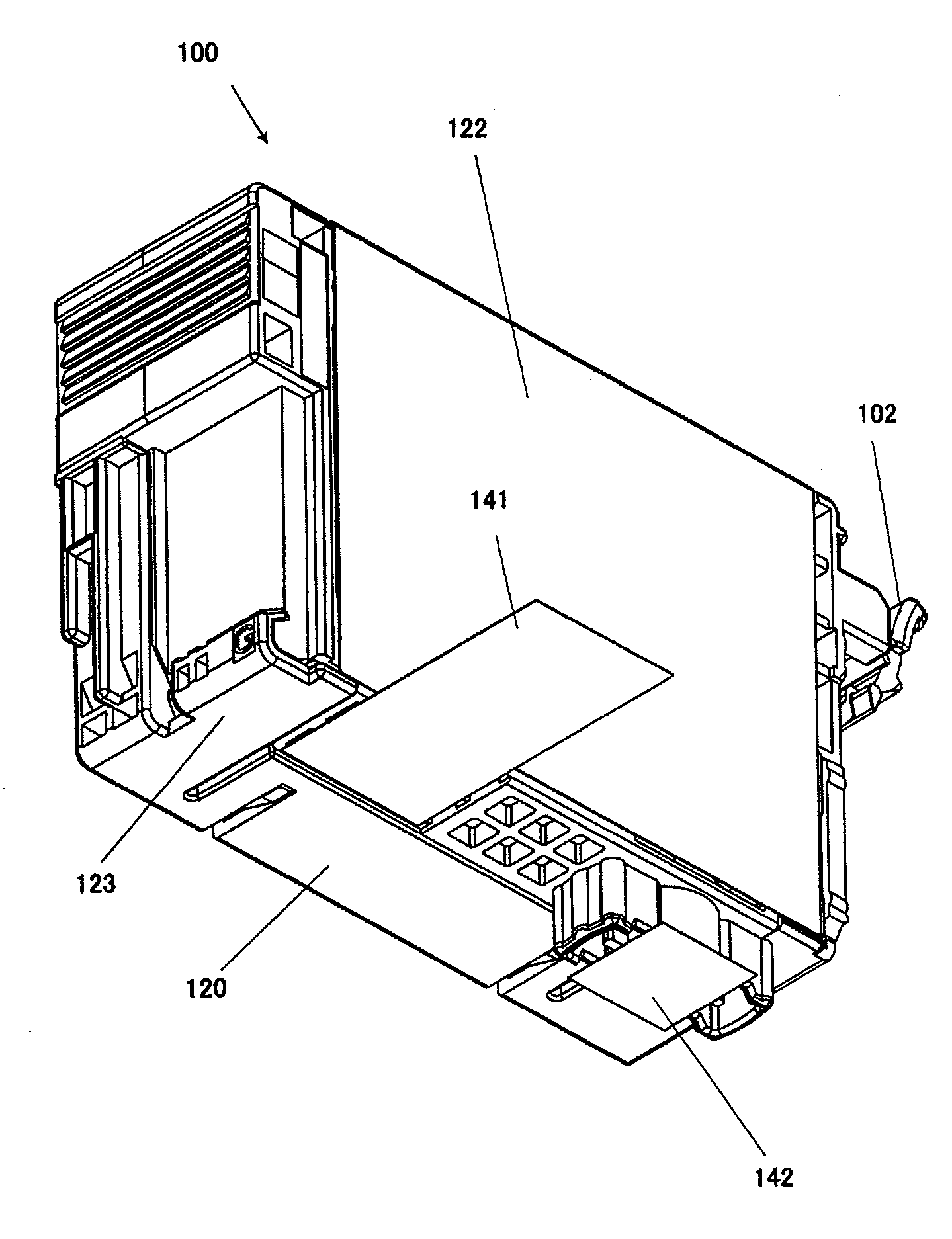
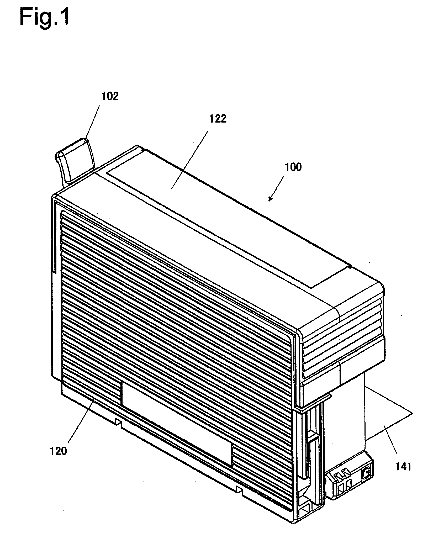
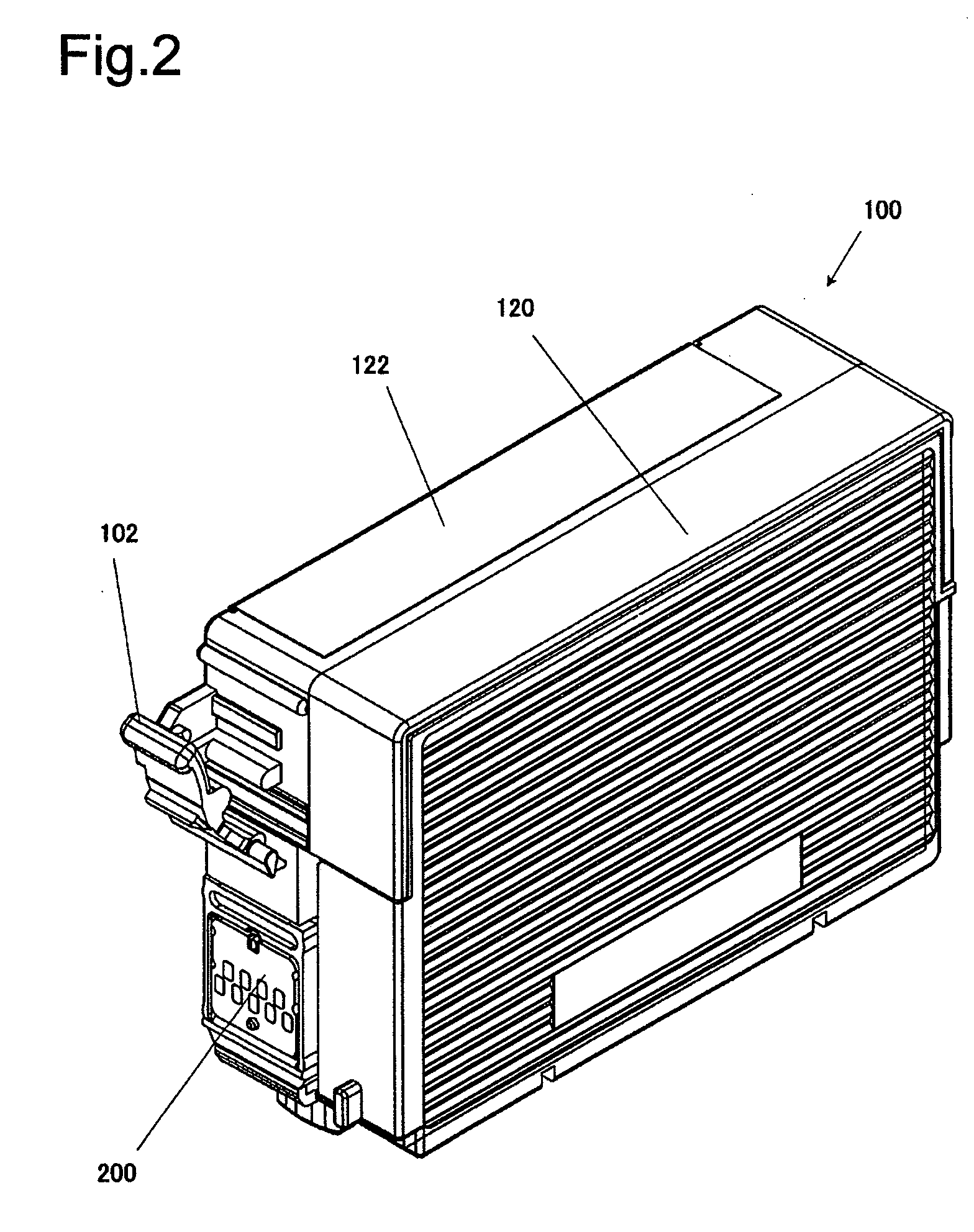
[0067]FIGS. 1 to 4 respectively depict an ink cartridge in an embodiment of liquid container according to the present invention, shown in external perspective view seen from the front side. FIGS. 5 to 8 respectively depict the ink cartridge of the embodiment in external perspective view seen from the rear side. FIG. 9 is a plan view of the ink cartridge of the embodiment; FIG. 10 is a front view; FIG. 11 is a left side view; FIG. 12 is a right side view; FIG. 13 is a rear view; and FIG. 14 is a bottom view. FIG. 15 is an exploded perspective view of the ink cartridge of the embodiment viewed from the...
PUM
| Property | Measurement | Unit |
|---|---|---|
| shape | aaaaa | aaaaa |
| pressure | aaaaa | aaaaa |
| height | aaaaa | aaaaa |
Abstract
Description
Claims
Application Information