
Deinterlacing and film and video detection with configurable downsampling

a deinterlacing and configurable technology, applied in the field of video deinterlacing, can solve the problems of inability to configure and/or flexible use of downsampling/decidation, lack of flexibility in trading off memory bandwidth and quality in the conventional deinterlacers, and loss of quality, so as to save memory bandwidth, reduce resolution fields, and reduce resolution fields

Active Publication Date: 2009-09-24
AVAGO TECH INT SALES PTE LTD
View PDF2 Cites 2 Cited by
  • Summary
  • Abstract
  • Description
  • Claims
  • Application Information

AI Technical Summary

Benefits of technology

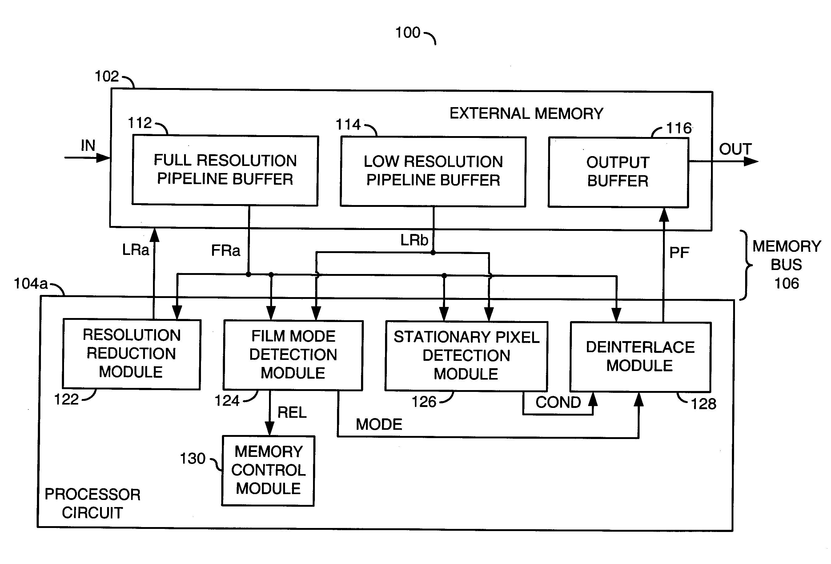
[0006]The objects, features and advantages of the present invention include providing a method and / or apparatus for implementing deinterlacing and film and video detection with configurable downsampling that may (i) save memory bandwidth, (ii) utilize reduced resolution fields for film mode detection, (iii) utilize reduced resolution fields for stationary pixel detection, (iv) maintain parallel pipelines of full resolution fields and reduced resolution fields in an external memory and / or (v) discard reduced resolution fields that are no longer useful from the external memory.

Problems solved by technology

Part of the challenge is a lack of flexibility to trade off memory bandwidth and quality in the conventional deinterlacers.
However, quality suffers when the subsampled / decimated fields are used for generating the progressive frames.
The existing solutions do not permit configurable and / or flexible use of downsampling / decimation.
For example, existing devices do not simultaneously store different resolution versions of the same field in the external memory.
Furthermore, the existing solutions are not configurable such that a first specified field resolution may be used for stationary pixel checking and / or film mode detection, while a second specified field resolution may be used for pixel generation by the deinterlacing unit.
Still further, the existing solutions are not configurable in the amount and type of decimation that is used depending on the type of film mode detected.

Method used


Image

  • Deinterlacing and film and video detection with configurable downsampling
  • Deinterlacing and film and video detection with configurable downsampling
  • Deinterlacing and film and video detection with configurable downsampling

Examples


Embodiment Construction

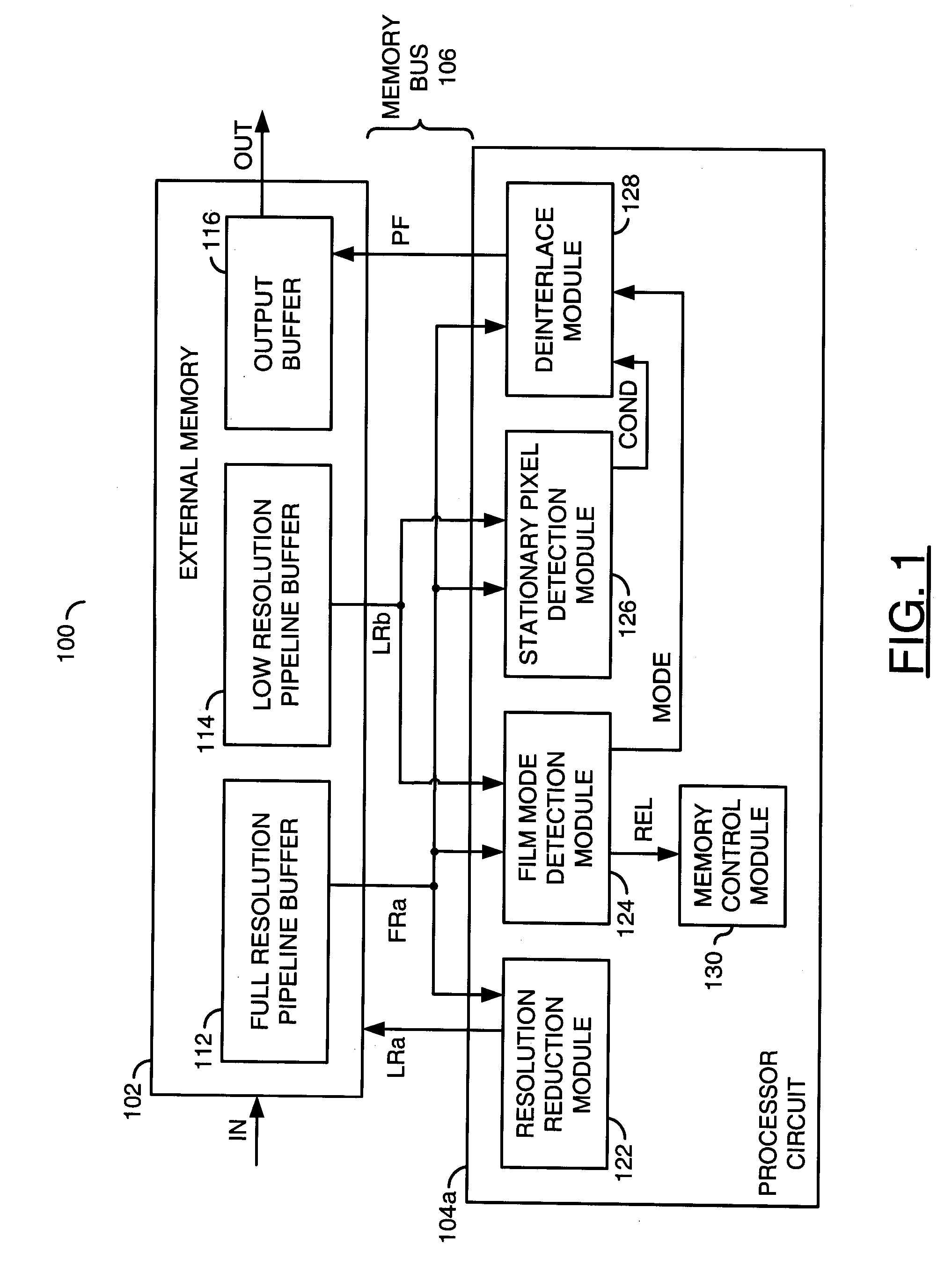
[0019]Referring to FIG. 1, a block diagram of a first example embodiment of a system 100 is shown in accordance with a preferred embodiment of the present invention. The system (or apparatus) 100 may implement a video deinterlacer. The system 100 is generally operational to deinterlace fields received in an input signal (e.g., IN) and presented progressive frames in an output signal (e.g., OUT). The system 100 generally comprises a memory (or module) 102 and a circuit (or module) 104a in communication with each other through a bus 106. Interlaced fields within the signal IN may be written into the memory 102. The progressive frames may be read from the memory 102 via the signal OUT.

[0020]The memory 102 may be operational to temporarily buffer the interlaced fields and the progressive frames. The memory circuit 102 may be implemented as a single data rate (SDR) dynamic random access memory (DRAM) or a double data rate (DDR) DRAM. Other memory technologies may be implemented to meet t...


PUM


Abstract

A system having a memory and a processor is disclosed. The memory may be arranged as (i) a first pipeline to buffer a plurality of full resolution fields and (ii) a second pipeline to buffer a plurality of low resolution fields. The processor is generally configured to (i) receive a particular one or more of the full resolution fields and a particular one or more of the low resolution fields from the memory and (ii) generate a film mode signal based on the particular low resolution fields, the film mode signal indicating a current mode among a plurality of pull-down modes related to a current field being deinterlaced.

Description

FIELD OF THE INVENTION [0001]The present invention relates to video deinterlacing generally and, more particularly, to a method and / or apparatus for implementing deinterlacing and film and video detection with configurable downsampling.BACKGROUND OF THE INVENTION [0002]The tasks of video deinterlacing and film-mode detection challenge conventional deinterlacers to achieve a best quality for a minimal memory bandwidth cost. Part of the challenge is a lack of flexibility to trade off memory bandwidth and quality in the conventional deinterlacers. High quality state-of-the-art video deinterlacers use multiple fields of video buffered in a memory to create progressive frames for display. Additionally, high quality state-of-the-art film mode detection units (that are typically used with deinterlacers) use multiple fields from the memory.[0003]Some existing deinterlacers and conventional film mode detectors are designed to use subsampled or decimated fields to save memory storage and band...

Claims


Application Information

Patent Timeline
Patent Type & Authority Applications(United States)
IPC IPC(8): H04N11/20
CPCH04N7/012H04N7/0147H04N7/0125
Inventor WINGER, LOWELL L.
Owner AVAGO TECH INT SALES PTE LTD
Learn More