Transmitting device, receiving device, transmitting method, receiving method and wireless communication system

a technology of transmitting device and receiving device, which is applied in the field of transmitting apparatus, receiving apparatus, transmission method, reception method and wireless communication system, can solve the problem of insufficient channel estimation accuracy, and achieve the effect of improving channel estimation accuracy, improving data rate, and maintaining channel estimation accuracy

Inactive Publication Date: 2009-09-24
PANASONIC CORP
View PDF5 Cites 45 Cited by
  • Summary
  • Abstract
  • Description
  • Claims
  • Application Information

AI Technical Summary

Benefits of technology

[0011]According to the present invention, it is possible to improve data rate while maintaining the accuracy of channel estimation, or improve the accuracy of channel estimation while maintaining data rate in MIMO-OFDM system.

Problems solved by technology

That is, if the number of pilot symbols is small, a lot of data can be transmitted, but sufficient accuracy of channel estimation is not expected.

Method used


Image

  • Transmitting device, receiving device, transmitting method, receiving method and wireless communication system
  • Transmitting device, receiving device, transmitting method, receiving method and wireless communication system
  • Transmitting device, receiving device, transmitting method, receiving method and wireless communication system

Examples


embodiment 1

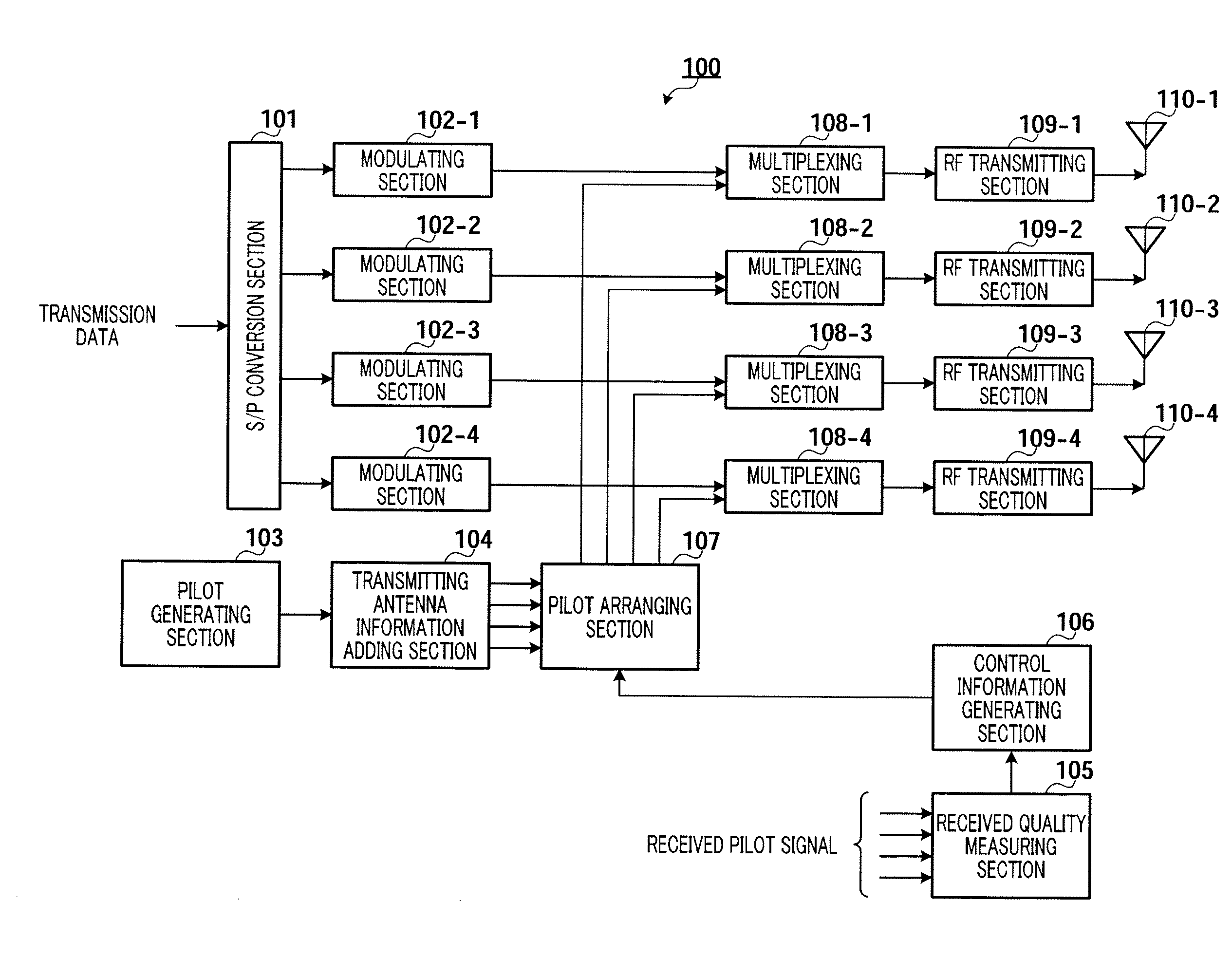
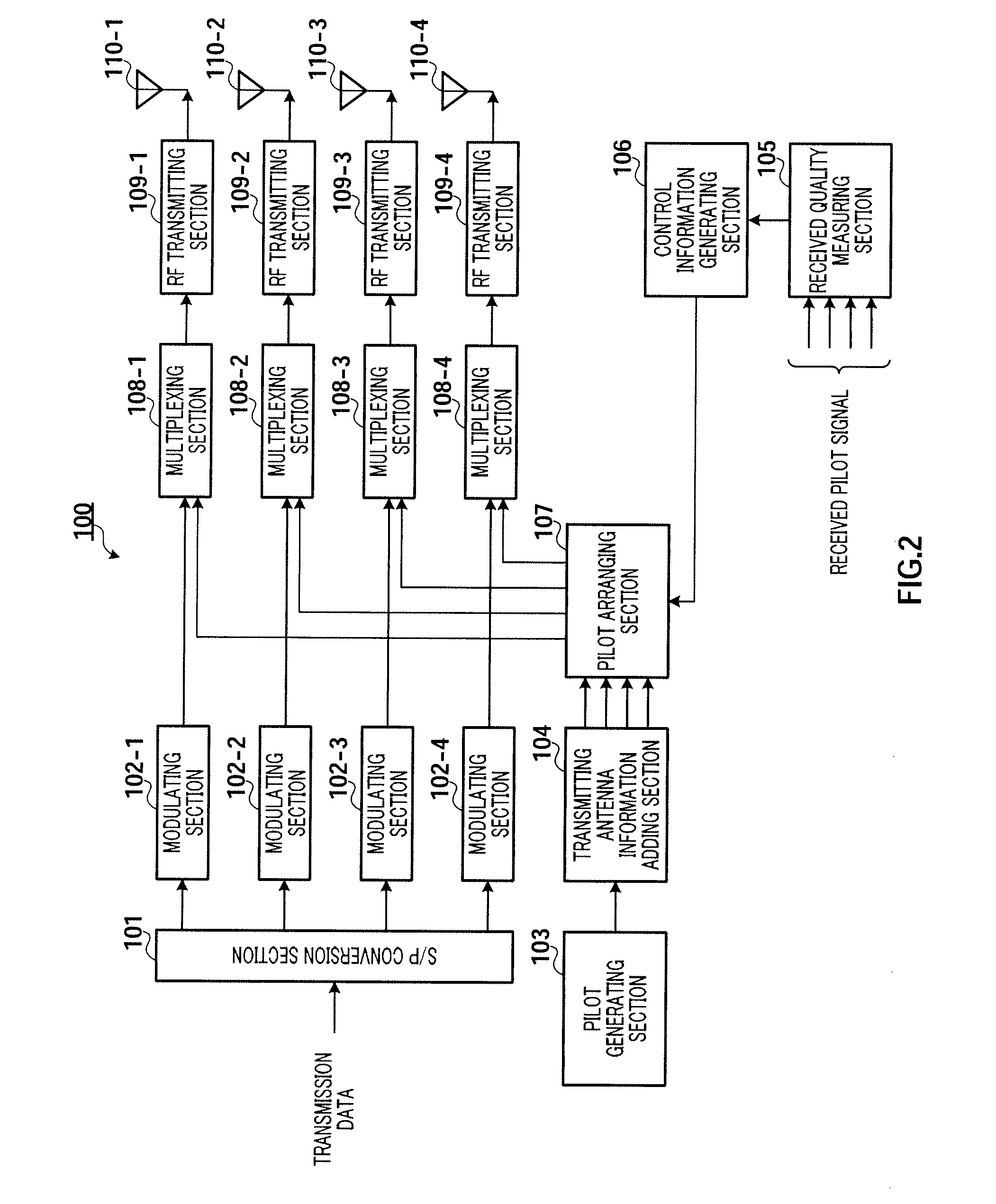
[0043]FIG. 2 is a block diagram showing the configuration of transmitting apparatus 100 according to Embodiment 1 of the present invention. In this figure, S / P conversion section 101 converts transmission data as input from a serial signal into parallel signals of four sequences, and outputs the transmission data of the sequences to modulating sections 102-1 to 102-4.

[0044]Modulating sections102-1 to 102-4 perform modulating processing of the transmission data outputted from S / P conversion section 101 and output the modulated signals to multiplexing sections 108-1 to 108-4, respectively.

[0045]Pilot generating section 103 generates pilot signals and outputs the generated pilot signals to transmitting antenna information adding section 104.

[0046]Transmitting antenna information adding section 104 sets the reference phase with the common pilot signal in the pilot signals outputted from pilot generating section 103, and, with respect to this reference phase, applies a phase rotation, wh...

embodiment 2

[0079]A case has been described above with Embodiment 1 where control information is transmitted using pilot signals by associating control information with combination information of the transmitting antennas and subcarriers used to transmit the pilot signals. Now, a case will be described with Embodiment 2 of the present invention where data is transmitted using pilot signals by associating data with combination information between the transmitting antennas and subcarriers used to transmit the pilot signals.

[0080]FIG. 15 is a block diagram showing the configuration of transmitting apparatus 300 according to Embodiment 2 of the present invention. FIG. 15 is different from FIG. 2 in that received quality measuring section 105 and control information generating section 106 are removed and pilot arranging section 107 is changed to pilot modulating section 301.

[0081]FIG. 16 is a block diagram showing the internal configuration of pilot modulating section 301 shown in FIG. 15. Referring...

embodiment 3

[0088]A case has been described above with Embodiment 2 where data is transmitted using pilot signals by associating data with combination information of the transmitting antennas and subcarriers used to transmit the pilot signals. Now, a case will be described below with Embodiment 3 where redundancy information is transmitted using pilot signals by associating the redundancy information with combination information of the transmitting antennas and subcarriers used to transmit the pilot signals.

[0089]FIG. 20 is a block diagram showing the configuration of transmitting apparatus 500 according to Embodiment 3 of the present invention. FIG. 20 is different from FIG. 15 in that coding section 501 and modulating section 502 are added and pilot modulating section 301 is changed to pilot modulating section 503.

[0090]Coding section 501 performs coding processing such as turbo coding of transmission data and generates information bits and redundancy bits. The generated information bits are ...


PUM


Abstract

Provided is a transmitting device which improves a data rate while maintaining channel estimation accuracy, or improves channel estimation accuracy while maintaining a data rate, in a MIMO-OFDM system. In the transmitting device, a transmitting antenna information adding section (104) adds transmitting antenna information to a pilot signal by performing different phase rotation to the separate pilot signal by transmitting antenna by having a common pilot signal as a reference phase. A pilot arranging section (107) is previously provided with, as a conversion table, a corresponding relationship between combination information of the transmitting antenna and a subcarrier to be used for transmission of the pilot signal and control information. The pilot arranging section (107) allocates the pilot signal outputted from the transmitting antenna information adding section (104) to the subcarrier to have the combination information in accordance with the control information.

Description

TECHNICAL FIELD[0001]The present invention relates to a transmitting apparatus, a receiving apparatus, a transmission method, a reception method and a wireless communication system in a MIMO-OFDM system adopting MIMO (Multiple Input Multiple Output) technique and OFDM (Orthogonal Frequency Division Multiplex) technique.BACKGROUND ART[0002]In the field of wireless cellular systems, which are represented by, for example, mobile phones, service modes become diverse, and transmitting large capacity data such as still images and movies in addition to voice data is in demand in recent years. On the other hand, a MIMO communication system which has high spectrum efficiency is studied actively.[0003]SDM (Space Division Multiplex) scheme is one of techniques to improve transmission rate in MIMO communication systems. SDM scheme refers to transmitting different signals from a plurality of antennas at the same time and demultiplexing the signals at the receiving side. Incidentally, channel inf...

Claims


Application Information

Patent Timeline
Patent Type & Authority Applications(United States)
IPC IPC(8): H04L27/28H04J99/00
CPCH04B7/0613H04B7/0684H04L1/0026H04L1/0041H04L1/06H04L5/0023H04W72/04H04L25/0204H04L25/0226H04L27/2613H04W24/00H04W48/08H04L5/0051H04L27/26134H04B7/0413H04L5/0091
Inventor IMAI, TOMOHIROHOSHINO, MASAYUKIYUDA, YASUAKIKIMURA, RYOHEIKOBAYAKAWA, YUICHI
Owner PANASONIC CORP
Why Eureka
Try Eureka