Intrajugular catheter

a technology of intrajugular catheter and caudal tube, which is applied in the field of intrajugular catheter, can solve the problems of complex and time-consuming procedure of cephalad insertion directly into the jugular bulb, inconvenient monitoring of brain oxygenation, and inability to accurately monitor blood oxygenation using the caudal tube techniqu

Active Publication Date: 2009-09-24
THE CLEVELAND CLINIC FOUND
View PDF3 Cites 17 Cited by
  • Summary
  • Abstract
  • Description
  • Claims
  • Application Information

AI Technical Summary

Problems solved by technology

During neurosurgical and other medical procedures, as well as for critically ill patients, monitoring brain oxygenation is a difficult but important task.
Monitoring of blood oxygenation by accessing the blood using the caudad technique is not accurate since blood coming from the brain into the jugular vein mi

Method used


Image

  • Intrajugular catheter
  • Intrajugular catheter
  • Intrajugular catheter

Examples


Embodiment Construction

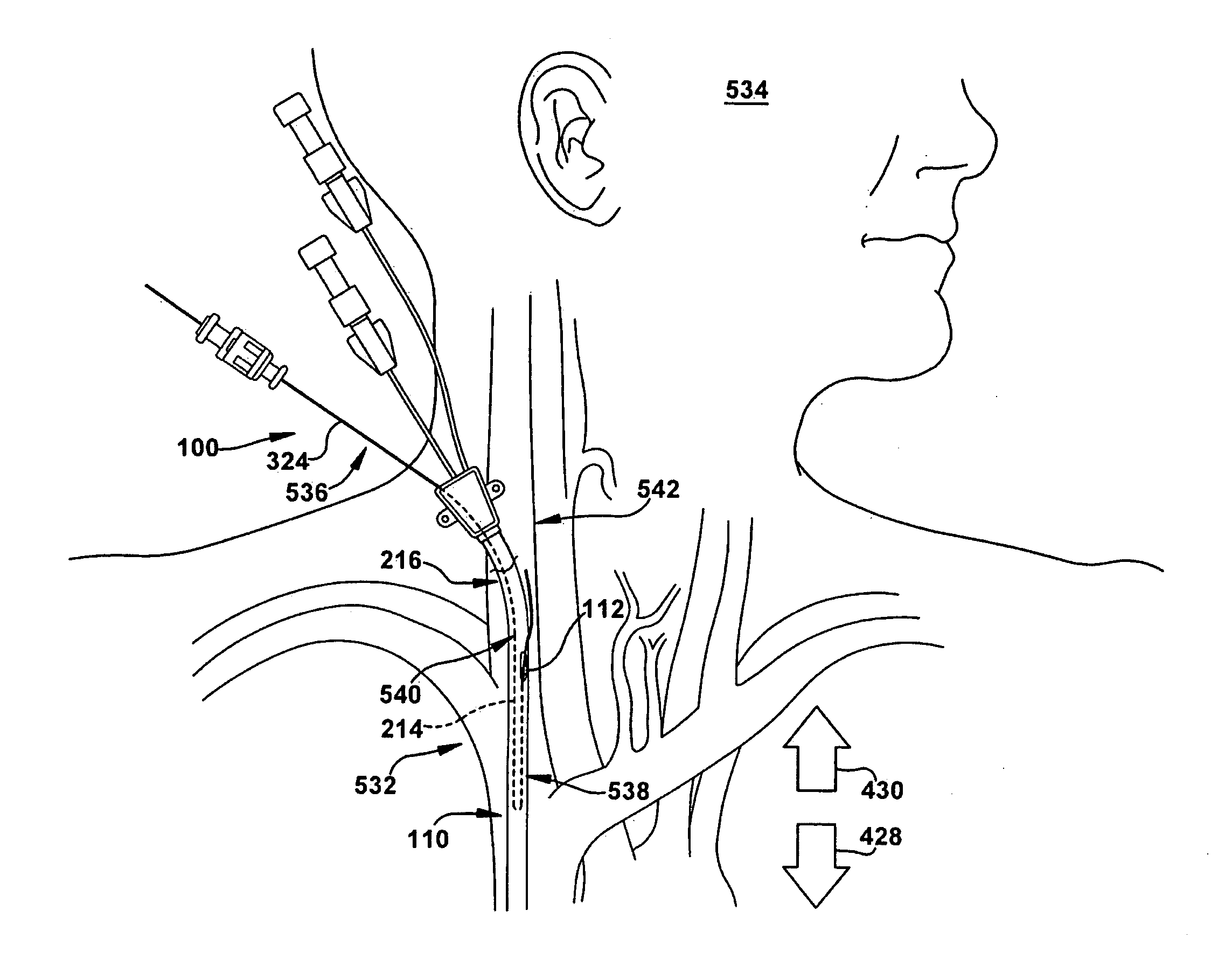
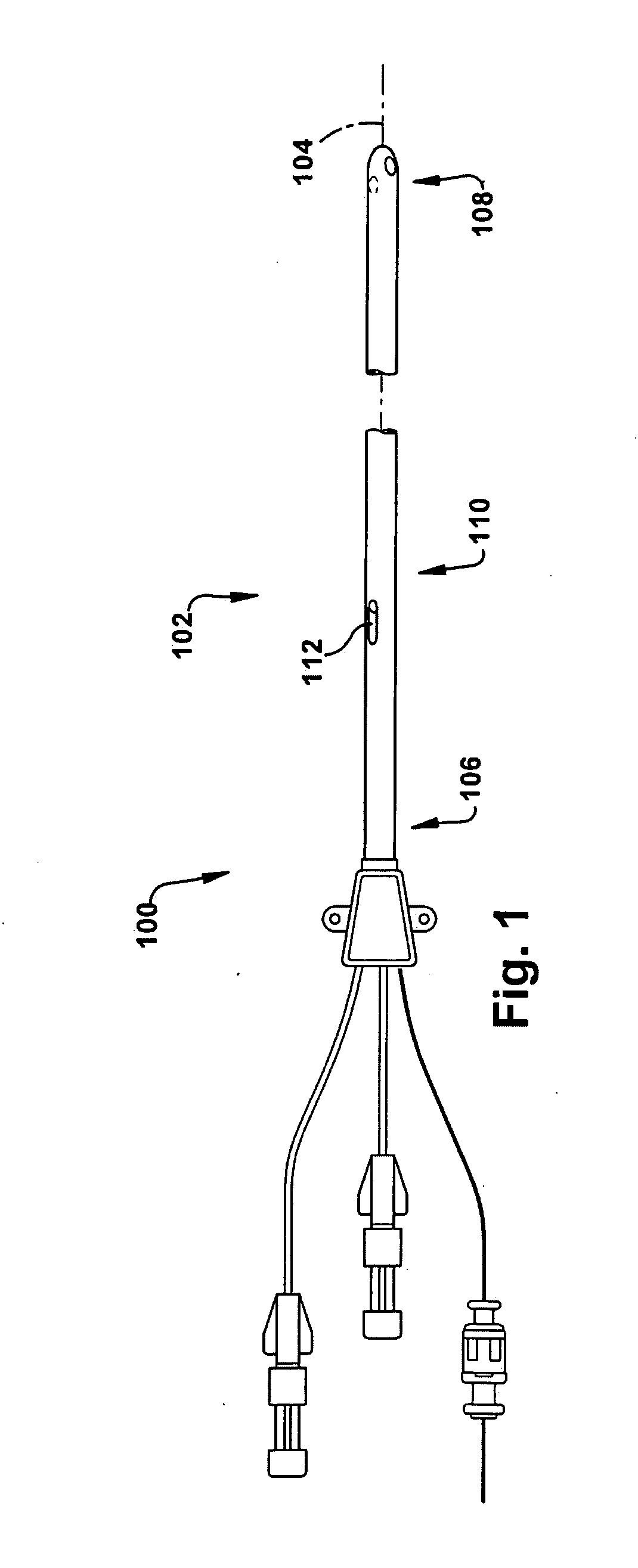
[0016]In accordance with the present invention, FIG. 1 depicts a catheter 100 for insertion into a vascular system of a patient and for directing fluid flow. As in all of the Figures, only a portion of the length of the catheter 100 is shown, for clarity. The external appearance of the catheter 100 is similar to that of known central venous access catheters. The catheter 100 has a catheter body 102 with a longitudinal axis 104 (only a portion shown, for clarity) and longitudinally spaced proximal and distal catheter ends 106 and 108, respectively, with an intermediate catheter portion 110 defined therebetween. An intermediate catheter outlet 112 is formed in the catheter body 102, located in the intermediate catheter portion 110, and spaced longitudinally from the distal end 108. The intermediate catheter outlet 112 is optionally adjacent the proximal end 106, as desired for a particular application of the catheter 100.

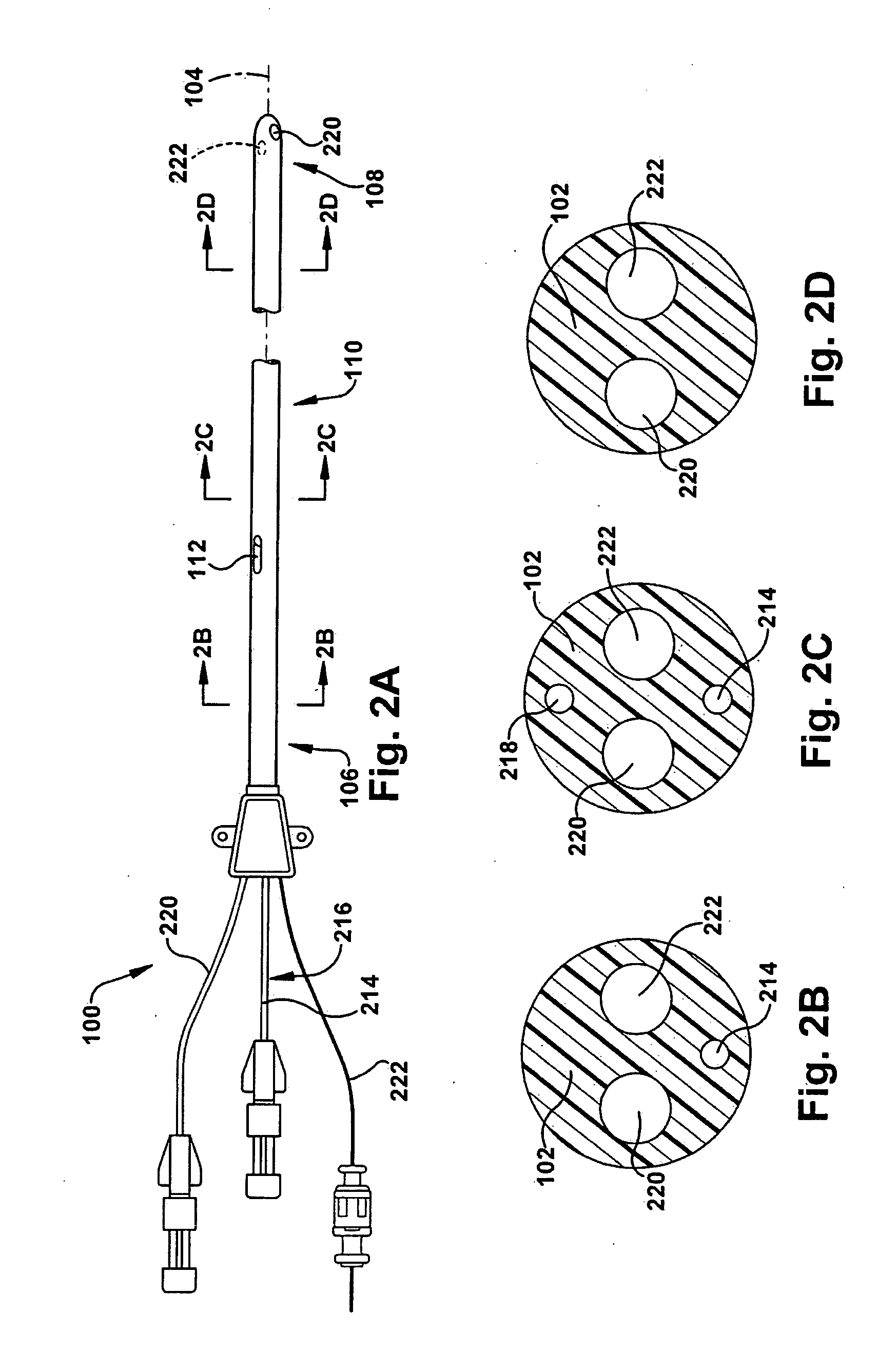
[0017]FIGS. 2A, 2B, 2C, and 2D depict a portion of the interior ...


PUM


Abstract

A catheter for insertion into a vascular system of a patient and for directing fluid flow includes a catheter body having a longitudinal axis and longitudinally spaced proximal and distal catheter ends with an intermediate catheter portion defined therebetween. An intermediate catheter outlet in the catheter body is located in the intermediate catheter portion and is spaced longitudinally from the proximal and distal catheter ends. A first lumen is defined within the catheter body and has longitudinally spaced proximal and distal first lumen ends with a reversing bend located therebetween, the first lumen providing fluid communication between the proximal catheter end and the intermediate catheter outlet. The reversing bend is located longitudinally between the intermediate catheter outlet and the distal catheter end. The reversing bend directs fluid flow to turn approximately 180° as the fluid flows through the first lumen. A method of using the catheter is also described.

Description

TECHNICAL FIELD[0001]The present invention relates to an apparatus and method for use of a catheter and, more particularly, to a catheter for insertion into a vascular system of a patient and for directing fluid flow, blood flow for sampling, and for insertion of an oxygenation monitor through the catheter for continuous oxygen monitoring.BACKGROUND OF THE INVENTION[0002]During neurosurgical and other medical procedures, as well as for critically ill patients, monitoring brain oxygenation is a difficult but important task. One way to determine this oxygenation is through monitoring the amount of oxygenated blood returning from the brain through the internal jugular venous system. Monitoring the jugular venous oxygen saturation level can give an early warning of hypoxia of the brain. An oximeter catheter can be introduced through a catheter placed in the patient's jugular vein to continuously monitor the oxygenation of this blood.[0003]Currently, catheters for measuring jugular venou...

Claims


Application Information

Patent Timeline
IPC IPC(8): A61M25/00A61B5/145
CPCA61M25/0023A61M2025/004A61M25/0032A61M25/0029A61B5/0205A61B5/026A61B5/14503
Inventor AVITSIAN, RAFI
Owner THE CLEVELAND CLINIC FOUND
Why Eureka
Try Eureka