Spinal Rod Guide For A Vertebral Screw Spinal Rod Connector Assembly

a technology of spinal rod and connector assembly, which is applied in the field of spinal rod construction, can solve the problems of being difficult and/or cumbersome to locate and mount a spinal rod onto the spinal rod connector of a vertebral bone screw, and achieve the effect of easy placement, easy to break or snap

Active Publication Date: 2009-09-24
LIFE SPINE INC
View PDF18 Cites 79 Cited by
  • Summary
  • Abstract
  • Description
  • Claims
  • Application Information

AI Technical Summary

Benefits of technology

[0010]An embodiment of the spinal rod guide comprises a first elongated arc portion that is attachable to a spine rod holder of a spinal rod bone screw assembly and a second elongated arc portion that is attachable to the spine rod holder of the spinal rod bone screw assembly. First and second longitudinal slots are defined between sides of the first and second arc portions and which extend from a top of the elongated arc portions to a bottom of the elongated arc portions. The two longitudinal slots are situated at diametrically opposite sides thereof. Each longitudinal slot aligns with a spinal rod slot of the spinal rod holder to thereby allow easy placement of the spinal rod into the spinal rod holder. Thereafter, the elongated arc portions provide direct communication and alignment with the top of the spinal rod holder by defining an elongated tube in order to receive a spinal rod holder drive screw for securing the spinal rod into the spinal rod holder. In this embodiment, the spinal rod guide is removed from the spinal rod holder after installation and securing of the spinal rod.
[0011]The present invention also provides a spinal rod guide assembly for mounting a spinal rod into a spinal rod holder of a vertebral bone screw assembly of the spinal rod guide assembly particularly, but not necessarily, for use in minimally invasive surgery. The spinal rod guide assembly includes a spinal rod guide that is initially attached to the spinal rod holder of the vertebral bone screw assembly. The spinal rod guide is configured to extend from an opening in a patient's body to the spinal rod connector, to receive a spinal rod therein, and thereafter accurately guide the spinal rod into the spinal rod connector. The spinal rod guide defines a guide tube for the introduction and placement of additional spinal rod components onto the spinal rod connector, particularly, but not necessarily, for securing the spinal rod into the spinal rod holder. The spinal rod guide is temporarily attached to the spinal rod connector in a manner that allows for easy detachment of the spinal rod guide from the spinal rod holder.
[0012]An embodiment of the spinal rod guide assembly includes a vertebral bone screw, a spinal rod holder pivotally coupled to the vertebral bone screw, and an elongated guide tube defined by first and second elongated arc portions that are attached onto a top of the spinal rod holder. The elongated guide tube has first and second longitudinal slots extending from a top of the elongated guide tube to a bottom of the elongated guide tube that align with first and second spinal rod slots of the spinal rod holder. The two longitudinal slots of the elongated guide tube and the two spinal slots of the spinal rod holder are situated at diametrically opposite sides. The slots allow easy placement of the spinal rod into the spinal rod holder. The elongated tube moreover provides direct communication and alignment with the top of the spinal rod holder in order to receive a spinal rod connector drive screw for securing the spinal rod into the spinal rod holder. The spinal rod guide is scored or otherwise connected at a junction between the spinal rod guide and the spinal rod holder such that the spinal rod guide is easily broken or snapped off from the spinal rod holder once installation of the spinal rod is complete.

Problems solved by technology

Because of this complicated procedure, it is fairly difficult and / or cumbersome to situate and mount a spinal rod onto a spinal rod connector of a vertebral bone screw.

Method used


Image

  • Spinal Rod Guide For A Vertebral Screw Spinal Rod Connector Assembly
  • Spinal Rod Guide For A Vertebral Screw Spinal Rod Connector Assembly
  • Spinal Rod Guide For A Vertebral Screw Spinal Rod Connector Assembly

Examples


Embodiment Construction

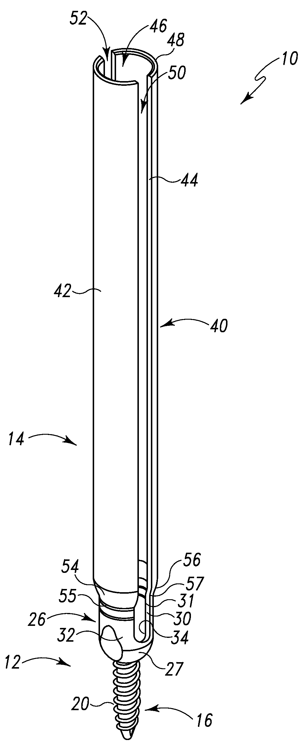
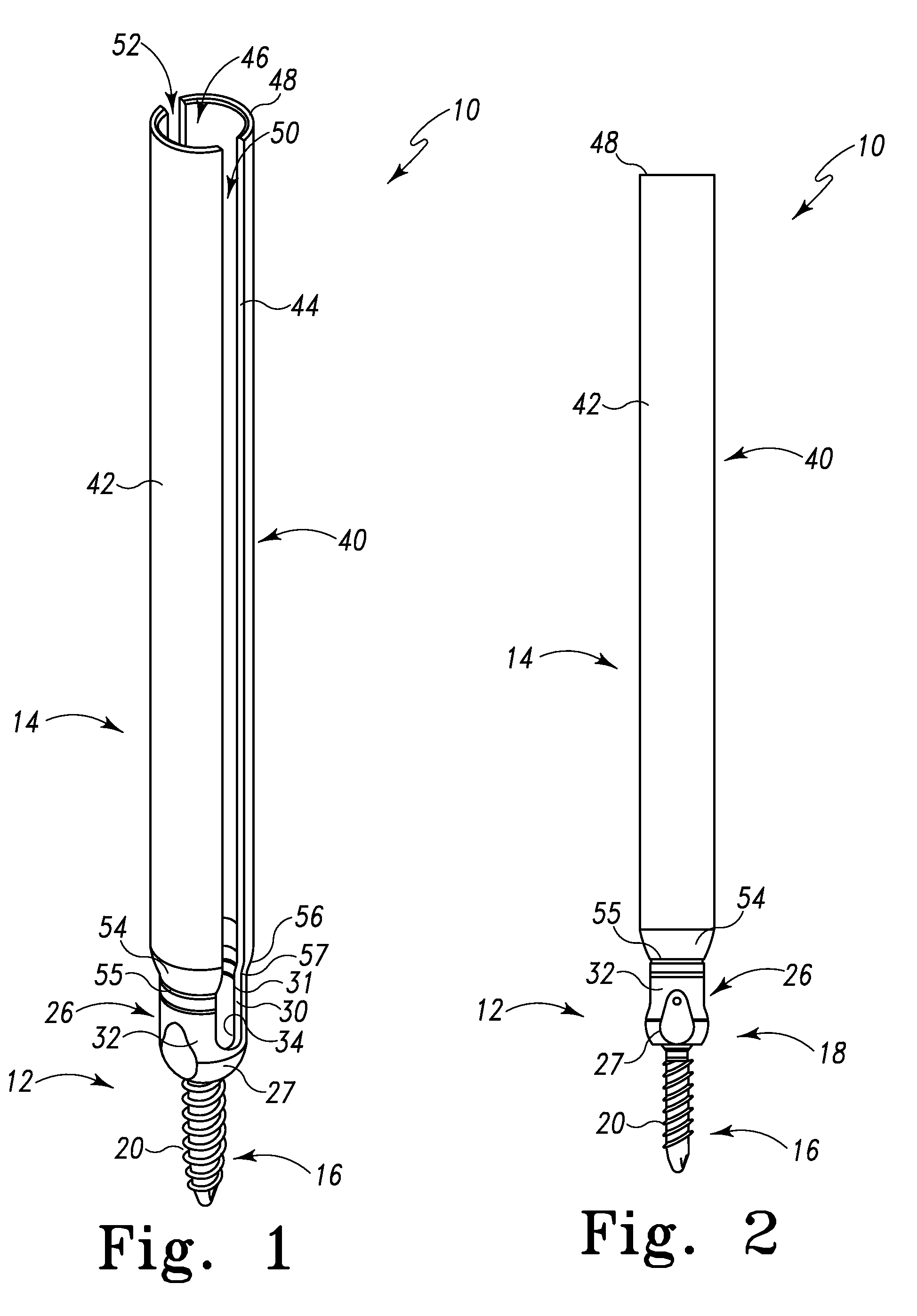
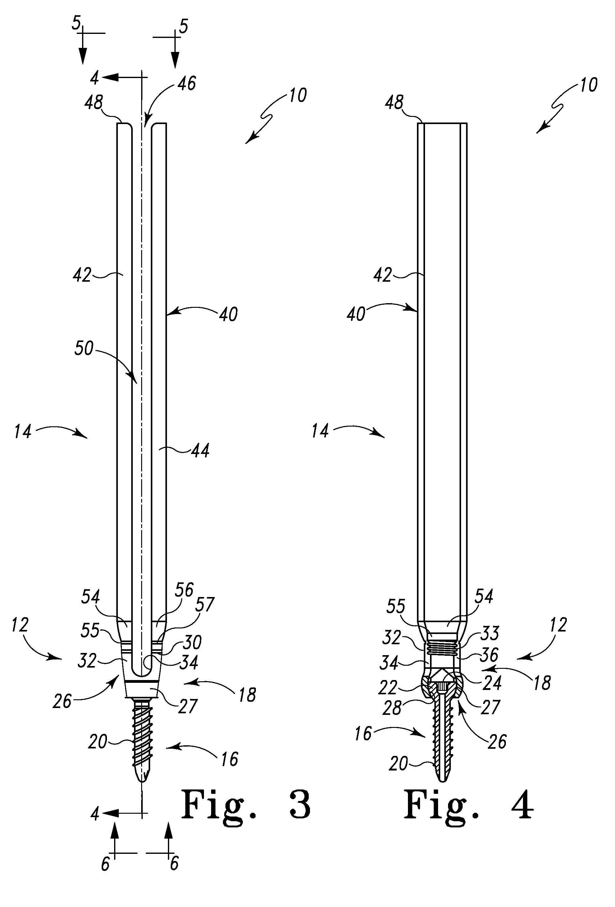
[0022]FIGS. 1-6 depict various views of a spinal rod guide / guide assembly generally designated 10 for the introduction, placement and securing of a spinal rod relative to vertebrae of a patient. The spinal rod guide assembly 10 is defined by a vertebral bone screw assembly 12 that is particularly, but not necessarily, a pedicle bone screw assembly (pedicle screw assembly) 12 and a spinal rod guide component 14. The spinal rod guide 10 is defined by the spinal rod guide component 14. The spinal rod guide / guide assembly 10 is made from titanium, stainless steel or another biocompatible material.

[0023]In one form, the spinal rod guide 10 may be considered as the spinal rod guide component 14 and, as such, the terms are interchangeable. In another form, the spinal rod assembly 10 may be considered as the spinal rod guide component 14 and the pedicle bone screw assembly 12 and, as such, the terms are interchangeable.

[0024]The pedicle bone screw assembly 12 is formed of a pedicle screw 16...


PUM


Abstract

A spinal rod guide and/or guide assembly is provided for mounting a spinal rod onto a spinal rod holder/connector of a vertebral bone screw. The spinal rod guide is configured to extend between an opening in a patient's body and the spinal rod holder of the vertebral bone screw assembly, to receive a spinal rod therein, and thereafter accurately guide the spinal rod into the spinal rod holder. The spinal rod guide is defined by a first elongated arc portion and a second elongated arc portion to define a guide tube for the introduction and placement of additional spinal rod components onto the spinal rod connector, particularly, but not necessarily, for securing the spinal rod into the spinal rod connector. The elongated arc portions are mountable or initially attached onto a top of a spinal rod holder of a spinal rod bone screw assembly. The elongated arc portions (tube) define first and second longitudinal slots extending from a top of the elongated arc portions to a bottom of the elongated arc portions. The two longitudinal slots are situated such as to be diametrically opposite one another. Each longitudinal slot aligns with a spinal rod slot of the spinal rod holder to thereby allow easy placement of the spinal rod into the spinal rod holder. Thereafter, the defined elongated tube provides direct communication and alignment with the top of the spinal rod holder in order to receive a spinal rod connector drive screw for securing the spinal rod into the spinal rod holder.

Description

RELATED APPLICATIONS[0001]This patent application claims the benefit of and / or priority to U.S. Provisional Patent Application Ser. No. 61 / 070,290 filed Mar. 21, 2008, entitled “Spinal Rod Guide For A Vertebral Screw Spinal Rod Connector Assembly” the entire contents of which is specifically incorporated herein by this reference.BACKGROUND OF THE INVENTION[0002]1. Field of the Invention[0003]The present invention relates to spine fixation components, constructs and assemblies and, more particularly, to a construct for the implantation of a spinal rod.[0004]2. Background Information[0005]Spinal orthopedic assemblies and constructs such as spine plates, spinal bone screw assemblies for spinal rods and other devices (spinal components) have made a profound contribution to the correction of spinal deformities, accidents and other problems in the thoracic, lumbar and sacral spine. These and other spinal devices are fixed to vertebrae using vertebral bone screws. Vertebral bone screws are...

Claims


Application Information

Patent Timeline
Patent Type & Authority Applications(United States)
IPC IPC(8): A61F5/00
CPCA61B17/7085A61B17/7083A61B17/7091
Inventor BUTLER, MICHAEL S.HARTSELL, BRIAN D.WEGRZYN, III, THOMAS J.
Owner LIFE SPINE INC
Why Eureka
Try Eureka