Diesel Exhaust Soot Sensor System and Method

a technology of exhaust soot sensor and diesel engine, which is applied in the direction of exhaust treatment, machines/engines, mechanical equipment, etc., can solve the problems of engine thermal efficiency decline, exhaust gases experience a significant pressure drop passing through the increasingly restrictive filter, and problems such as problems such as the effect of affecting the operation of the engin

Inactive Publication Date: 2009-10-01
WOODWARD GOVERNOR CO
View PDF19 Cites 37 Cited by
  • Summary
  • Abstract
  • Description
  • Claims
  • Application Information

AI Technical Summary

Benefits of technology

[0009]In view of the above, embodiments of the present invention provide new and improved systems and methods for determining soot accumulation in a DPF to more effectively initiate a regeneration process to burn off the accumulated soot in the DPF in a safe and controlled manner, and to effectuate same.

Problems solved by technology

While such devices provide a significant environmental benefit, as with any filter, problems may occur as the DPF continues to accumulate these particulates.
After a period of time the DPF becomes sufficiently loaded with soot that the exhaust gases experience a significant pressure drop passing through the increasingly restrictive filter.
As a result of operating with an overly restrictive filter, the engine thermal efficiency declines because the engine must work harder and harder simply to pump the exhaust gases through the loaded DPF.
Besides the reduced thermal efficiency, a second and potentially more dangerous problem may occur.
Because the soot accumulated in the DPF is flammable, continued operation with a loaded DPF raises the serious potential for uncontrolled exhaust fires if and when the accumulated soot is eventually ignited and burns uncontrollably.
Typically the acceptable regeneration range is from 600 to 900° C. Temperatures below this range are insufficient to ignite the accumulated soot, and temperatures above this range may cause thermal damage to the filter media.
If regeneration is initiated too soon when the DPF is only lightly loaded, the process will be inefficient.
If the regeneration is not initiated until the DPF is heavily loaded, the overall engine efficiency would have been unduly reduced as discussed above and there is a risk that the soot may self-ignite and / or that the burn may be unsafe and uncontrolled.
These sensors and control algorithms are used to estimate the soot loading of the DPF so that regeneration can be initiated only after soot loading could cause an engine efficiency reduction but before excessive loading occurs actually resulting in such an efficiency reduction and raising the potential for self-ignition.

Method used


Image

  • Diesel Exhaust Soot Sensor System and Method
  • Diesel Exhaust Soot Sensor System and Method
  • Diesel Exhaust Soot Sensor System and Method

Examples


Embodiment Construction

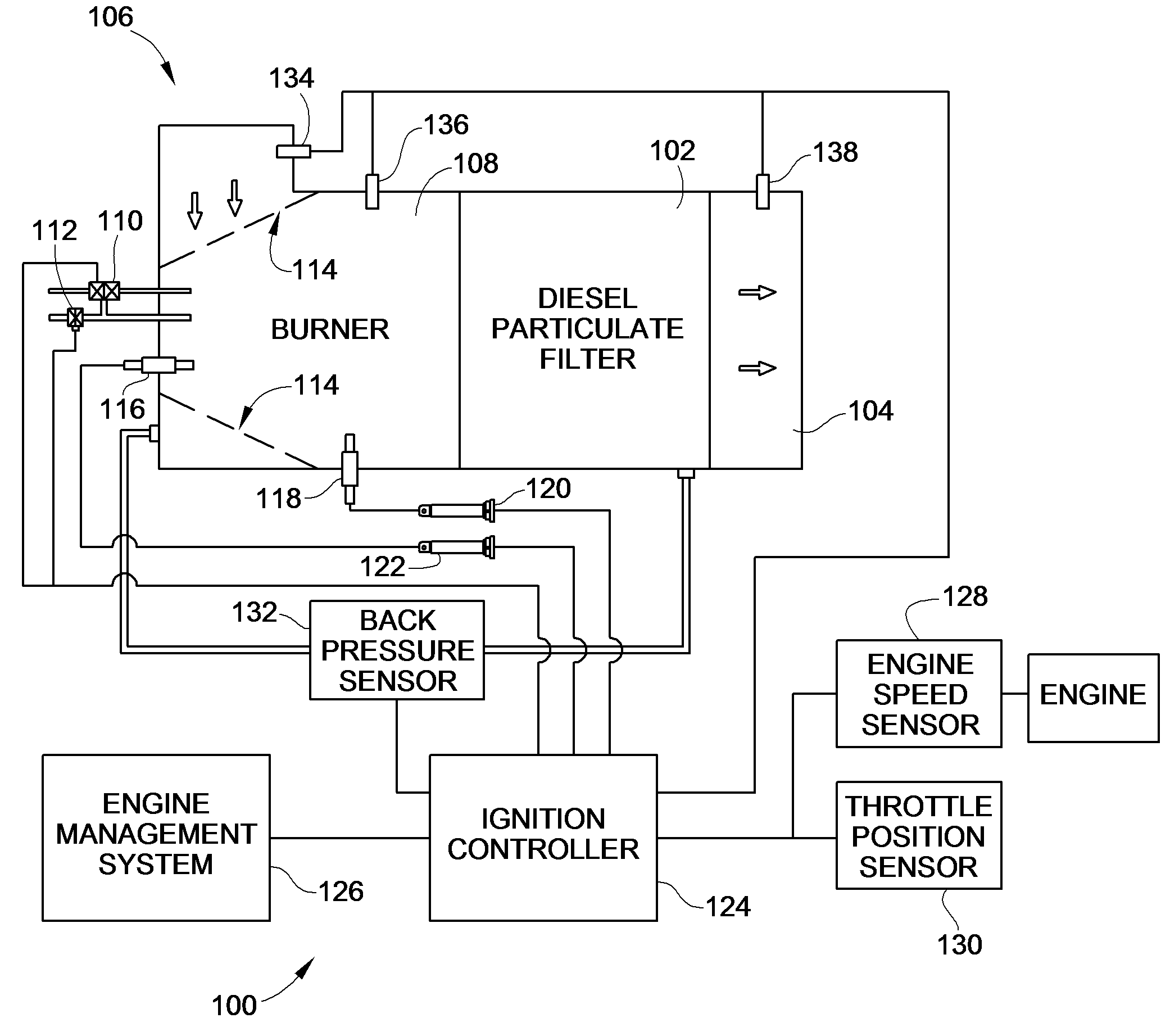
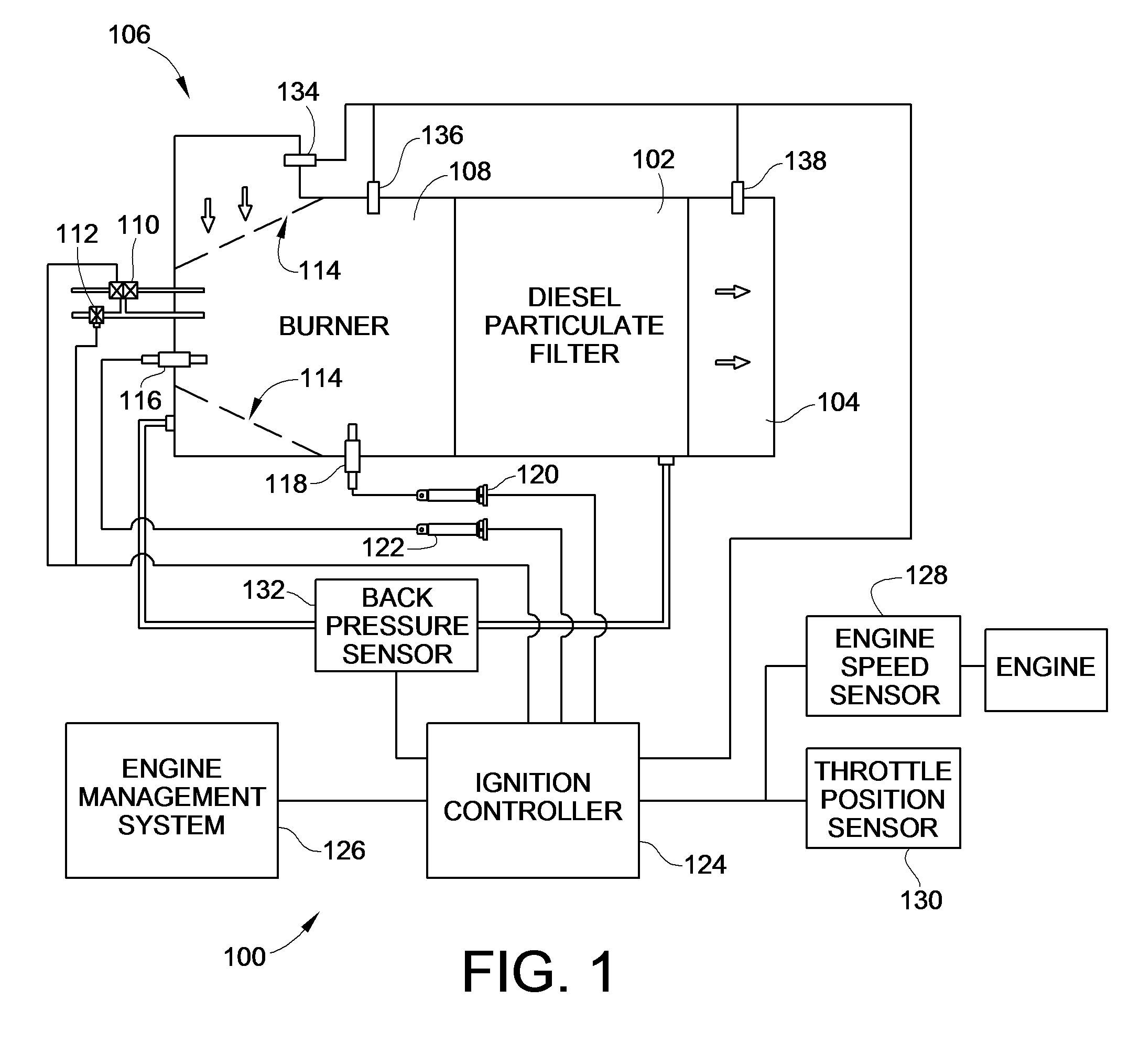
[0025]Turning now to the drawings, there is illustrated in FIG. 1 an embodiment of a system 100 constructed in accordance with the teachings of the present invention that is capable of determining an appropriate time to initiate regeneration of a diesel particulate filter (DPF) 102. As discussed above, the DPF 102 is installed before or upstream of an exhaust outlet 104 to filter out particulates from the diesel engine exhaust. In order to clean the collected particulates, e.g. soot, off of the DPF 102, a burner 108 may be used upstream of the DPF 102 but downstream from the exhaust inlet 106 from the engine. Such a burner 108 may be any source of auxiliary heat, such as a fuel fired burner, and electrical burner, RF burner, DOC, or via modified engine operation. The engine exhaust gases flow through openings 114 of the burner 102 and through the DPF 102 before exiting into the environment via the exhaust outlet 104.

[0026]In a fuel fired burner 108 fuel and air are supplied via a fu...


PUM


Abstract

Systems and methods to determine when regeneration of a diesel particulate filter (DPF) are presented. Such determination is made by indirectly determining soot accumulation in the DPF by monitoring soot accumulation on a regeneration burner spark plug based on the correlation between spark plug fouling and DPF soot loading. An ion current sensing circuit is used during periods of no flame to determine soot loading on the spark plug. When soot loading on the spark plug approaches an amount that could cause fouling of the spark plug, the ignition controller initiates a hot spark to burn the soot off the spark plug. The number of such cleaning events is tracked and used to determine when the DPF soot loading is at a level that regeneration should be initiated. Temperature rise across the DPF is monitored and used to adjust the number spark plug cleaning events needed before initiating regeneration.

Description

FIELD OF THE INVENTION[0001]This invention generally relates to diesel particulate filter (DPF) systems and more specifically to a system and method for determining soot accumulation in a DPF to more effectively initiate a regeneration process to burn off the accumulated soot in the DPF.BACKGROUND OF THE INVENTION[0002]Increasing environmental restrictions and regulations are causing diesel engine manufacturers and packagers to develop technologies that improve and reduce the impact that operation of such engines have on the environment. As a result, much design work has gone into the controls that operate the combustion process within the engine itself in an attempt to increase fuel economy and reduce emissions such as NOx and particulates. However, given the operating variables and parameters over which a diesel engine operates and given the tradeoff between NOx and particulate generation, many engine manufacturers and packagers have found it useful or necessary to apply exhaust a...

Claims


Application Information

Patent Timeline
Patent Type & Authority Applications(United States)
IPC IPC(8): F01N3/025
CPCF01N2570/10F01N3/025
Inventor GENDRON, THOMAS A.VAN DYNE, ED
Owner WOODWARD GOVERNOR CO
Why Eureka
Try Eureka