Apparatus for cleaning a diesel particulate filter with multiple filtration stages

Active Publication Date: 2006-04-11
HOLTZHEUSER MORGAN CHRISTINA +1
View PDF28 Cites 60 Cited by
  • Summary
  • Abstract
  • Description
  • Claims
  • Application Information

AI Technical Summary

Benefits of technology

[0038]Another embodiment of the system comprises additional items for automating the process, for improving the cleaning efficiency, and for determining when the cleaning process is complete. The cleaning fluid may be heated through in-line electrical means, combustion means, or other techniques as known in the art. A flexible coupling is attached between the heater section and a flow sensing element to absorb shock and movement. A flow sensing element monitors the flow rate of cleaning fluid to the filter face, using methods known in the art (hot wires, measurement o

Problems solved by technology

In these cases, the filter can become clogged with PM and potentially reduces the performance of the engine.
In addition, a filter with a high soot load has a higher chance of permanent damage through uncontrolled regeneration than one with low soot load.
In these cases of insufficiently high operating temperature, regular removal of the soot may be required.
Some of these approaches are overly complex, others are ineffective at removing tightly bound particulate, and others can lead to high PM emissions during the cleaning process.
This method is imprecise, potentially dangerous (compressed air hazards), requires the full attention of an operator, and if improperly performed can lead to emission of PM from the filter end as well as a poorly cleaned filter.
Heating the dirty filter in an oven to a high temperature can effectively remove the carbon-based particles, but requires significant energy input and does not remove the inorganic ash.
Blowers of the appropriate size are expensive and noisy, and the technique may not remove the tightly bound material.
Many systems for cleaning industrial devices utilize a combination of liquid flow and ultrasound, which may be effective, but can be overly expensive In addition, the cleaning liquid can damage the catalytic coating or the matting material which secures the catalyst within its metal housing.
However, many catalysts and their matting material are se

Method used


Image

  • Apparatus for cleaning a diesel particulate filter with multiple filtration stages
  • Apparatus for cleaning a diesel particulate filter with multiple filtration stages
  • Apparatus for cleaning a diesel particulate filter with multiple filtration stages

Examples


first embodiment

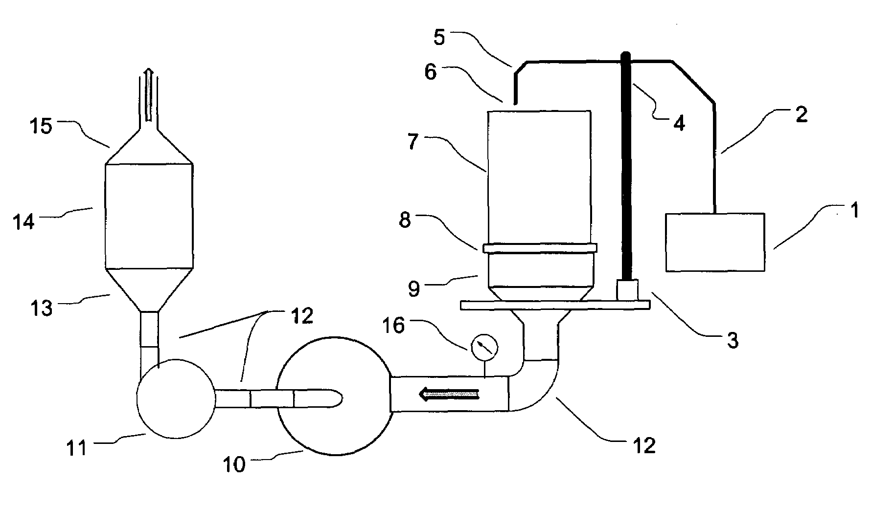
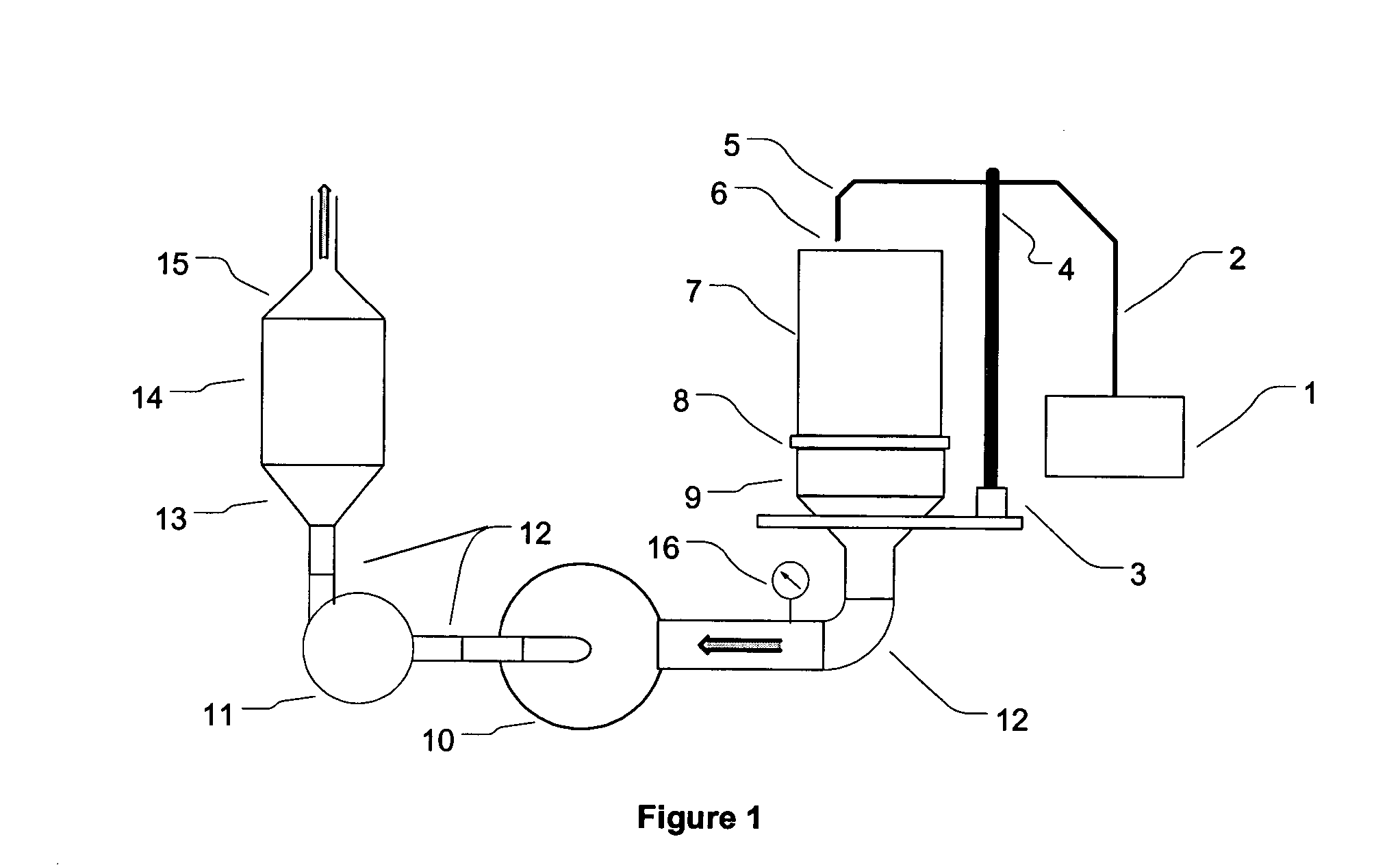
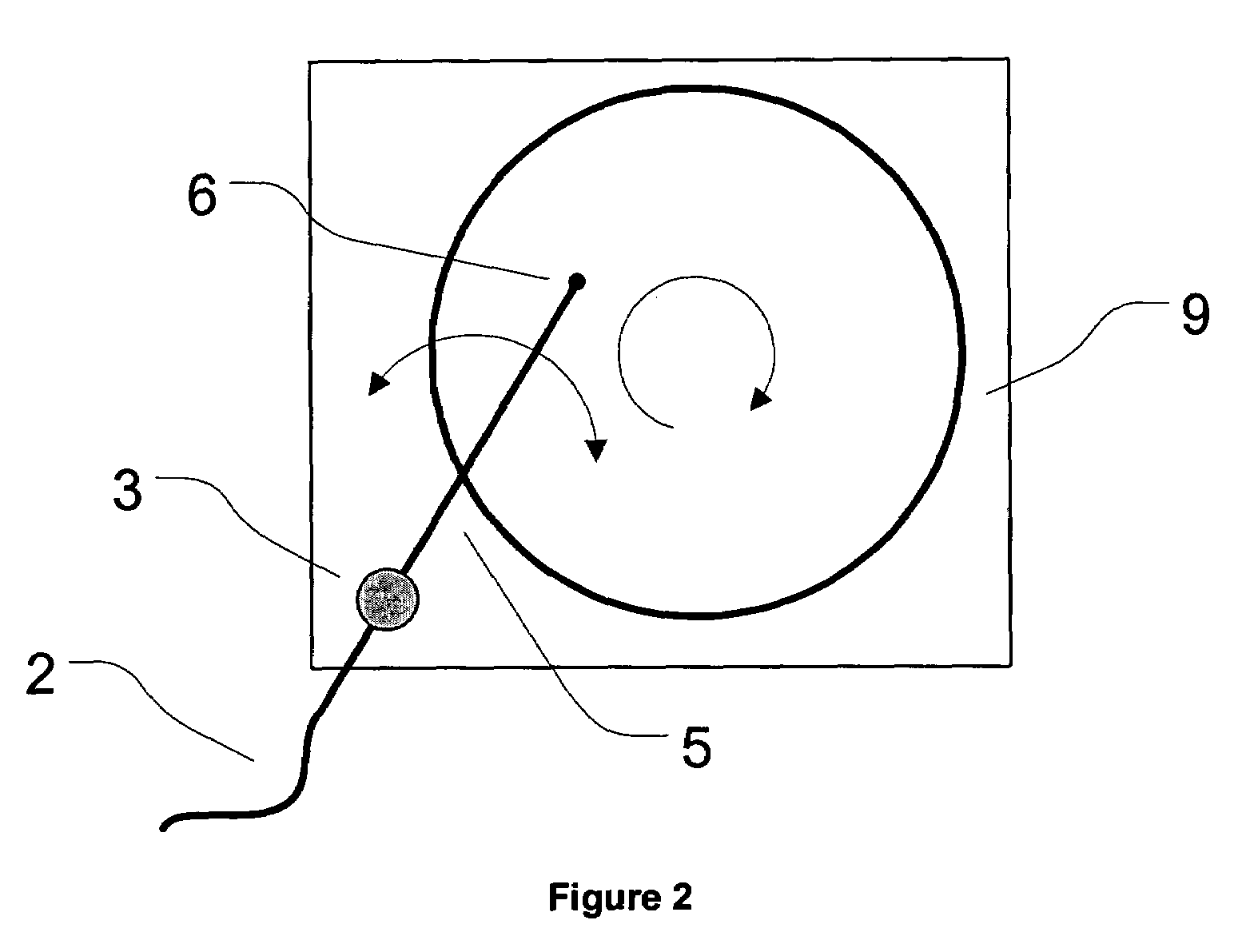
[0059]the invention is directed to the feature of filter rotation and arc-like jet motion. High pressure cleaning fluid is obtained from a source 1 and transferred through ducting 2. The filter cleaner uses a turntable 9 and swing arm 5 with an air nozzle 6 to direct high pressure cleaning fluid to the filter face. A schematic of the overall system is shown in FIG. 1, and the nozzle translation device is detailed in FIG. 2. In FIG. 2, the filter cleaner may optionally have one or two motors. A one motor system will have a single motor 3 which can be used in combination with reduction gears (not shown) to control both the arm 5 and turntable 9 movement. A two motor system will have independent motors for the nozzle arm 5 and the filter turntable 9. In a typical cleaning procedure, the filter 7 is attached to the rotation table with an adapter ring 8 and is locked in the starting position. When the start button is depressed, the main power relay activates, and in turn activates the fl...

third embodiment

[0062]the invention is directed to a rotating arm. This embodiment is illustrated in FIG. 7 and FIG. 8. The nozzle 728 and delivery tube 729 are attached to the cleaning fluid source 2 with a standard commercial rotating coupling 726 (available from most industrial suppliers). A suitable bearing 727 attaches the delivery tube 729 to the frame 723. The frame is attached to the flanged-connection 8, which then attaches to the DPF 7. During a cleaning cycle, the nozzle 728 rotates about the central axis of the filter, thus periodically exposing a narrow strip of the filter to cleaning fluid.

[0063]Another embodiment of the system comprises additional items for automating the process, for improving the cleaning efficiency, and for determining when the cleaning process is complete (FIG. 9). The cleaning fluid is be heated through in-line electrical or combustion means 22. Heating may aid particulate removal by volatilizing part of the particulate, and decreasing the viscosity of any liqui...


PUM

PropertyMeasurementUnit
Forceaaaaaaaaaa
Pressureaaaaaaaaaa
Flow rateaaaaaaaaaa

Abstract

The present invention is directed to a filter cleaning device, in particular, diesel particulate filters. In one embodiment, the device comprises a source of high pressure fluid and means to transport the fluid to a nozzle or nozzles; an actuator for moving the nozzles; a controller with logic for instructing the actuator to automatically move the nozzle or nozzles across the surface of the filter; a collection device and suction device downstream of the filter; and ducting to transport the fluid between parts of the system. In one embodiment, a second collection device is used downstream of the suction device to provide additional particulate removal. There are three methods proposed for providing high pressure cleaning fluid to the filter face: 1) rotating the filter and rotating the jet about an axis outside of the filter; 2) moving a nozzle in two perpendicular directions (i.e., x-y); and 3) rotating a rectangular nozzle about the central axis of the filter.

Description

[0001]This application claims the benefit of priority from commonly assigned, U.S. Provisional Patent Application Ser. No. 60 / 405,437 filed Aug. 23, 2002. This application is fully incorporated herein by reference for all purposes.BACKGROUND OF THE INVENTION[0002]a) Field of the Invention[0003]This application is directed to a device for cleaning filters, and in particular, diesel particulate filters.[0004]b) Description of Related Art[0005]A diesel particulate filter removes organic and inorganic particulate matter (PM) from the exhaust gas stream of an engine. The organic particulate is a complex blend of carbon, hydrogen and oxygen, and is a result of incomplete combustion of the diesel fuel in the cylinder. The inorganic portion of the PM has its source in the additives in the lubrication oil or fuel, and material eroded from the engine surfaces. Under optimal circumstances, the organic PM will fully combust during filter regeneration and thus leave the filter as gaseous CO2 and...

Claims


Application Information

Patent Timeline
IPC IPC(8): B01D35/143B01D35/16B01D41/04B01D46/42
CPCB01D41/04
Inventor STREICHSBIER, MICHAELLEMKE, RICHARD G.WEHRLEY, DEANEDGAR, BRADLEY L.RUMMINGER, MARC D.
Owner HOLTZHEUSER MORGAN CHRISTINA
Why Eureka
Try Eureka