Electrical cable harness and assembly for transmitting ac electrical power

a technology of electrical power transmission and electrical cable, applied in the direction of insulated conductors, cables, coupling device connections, etc., can solve the problems of inefficiency of the system, power loss, module-to-module mismatch, etc., and achieve the effect of facilitating communication

Inactive Publication Date: 2009-10-01
FTC SOLAR INC
View PDF22 Cites 64 Cited by
  • Summary
  • Abstract
  • Description
  • Claims
  • Application Information

AI Technical Summary

Benefits of technology

[0019]A still further object of the invention is to provide a power generating assembly including a plurality of the aforesaid AC modules in communication with a junction box, and a line-alternating cable harness assembly which facilitates the communication.
[0020]A still further object of the invention is to provide the aforesaid power generating assembly wherein selected components of the power generating assembly and the cable harness assembly and the junction box are provided with connector means configured to physically engage and interlock with complementary connector means, the connector means being configured so as not to engage with each other unless properly paired, such that such connectors, and thereby the other components of the system, cannot be inappropriately interconnected. Any of the connecter / cable harness devices provided herein can be paired with any other like connector / cable harness and effect a correct connection for a buss.

Problems solved by technology

This system suffers from inefficiencies, such as module-to-module mismatch and power loss due to varying module orientations and significant shading losses.
In addition to adding cost, the junction box may require a roof penetration or may require a visible metal clad conduit, which installers try to minimize because of roof warranty issues and aesthetics.
Higher temperature ratings and larger wire gauge increase the cost of the AC module cable harness.
Therefore, as n increases, the cost of the AC module cable harness increases.
A limitation of the current AC module physical layout is that the junction box must be placed in a physical location that assures that it will accommodate the desired physical layout and electrical requirements of the AC module string.

Method used


Image

  • Electrical cable harness and assembly for transmitting ac electrical power
  • Electrical cable harness and assembly for transmitting ac electrical power
  • Electrical cable harness and assembly for transmitting ac electrical power

Examples


Embodiment Construction

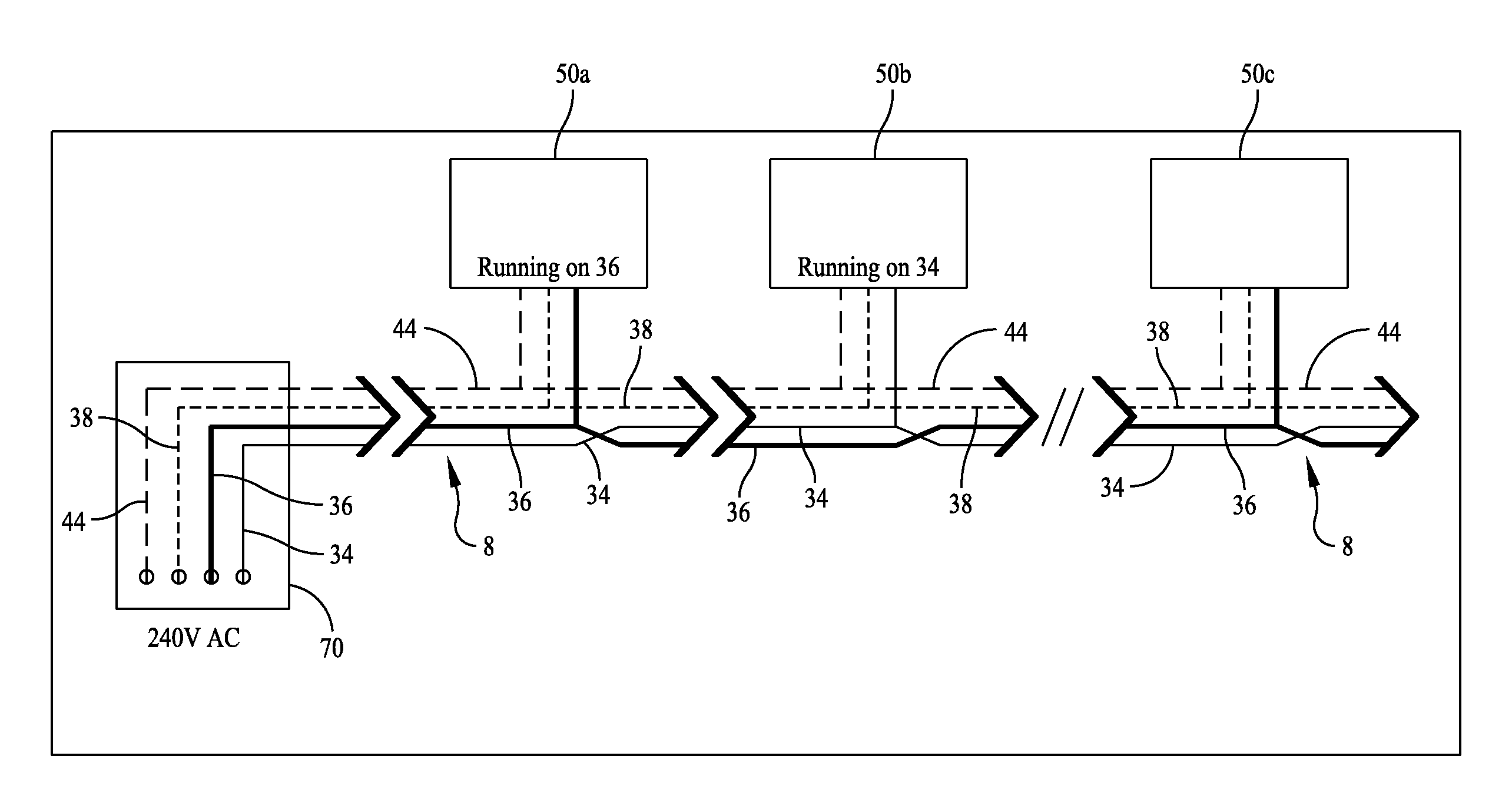
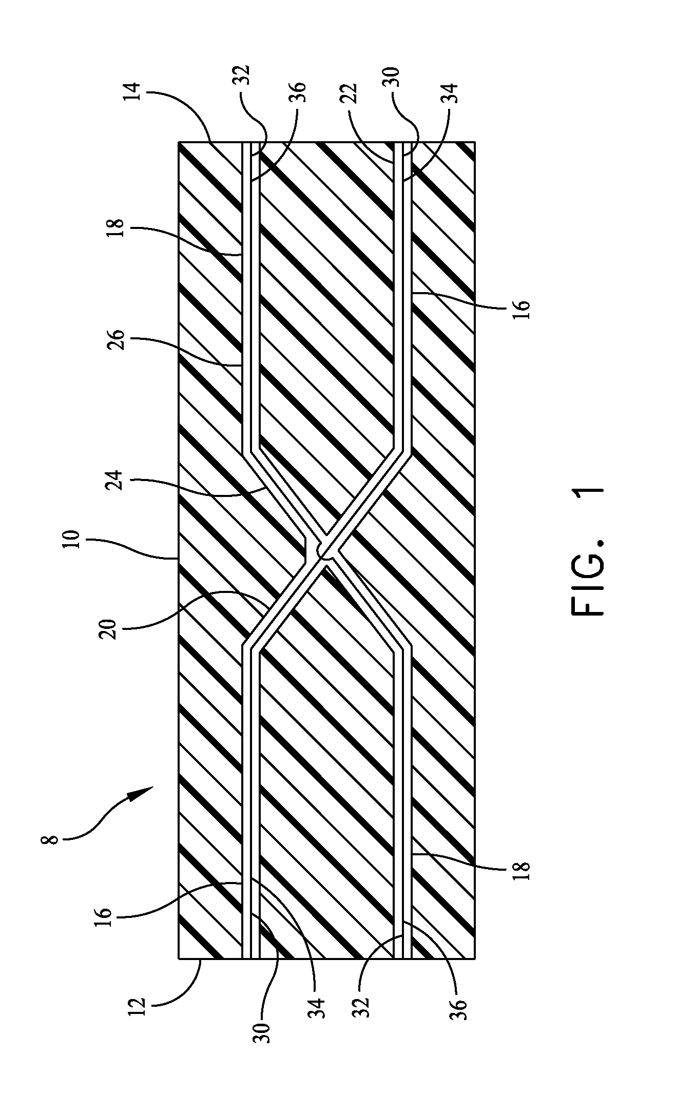
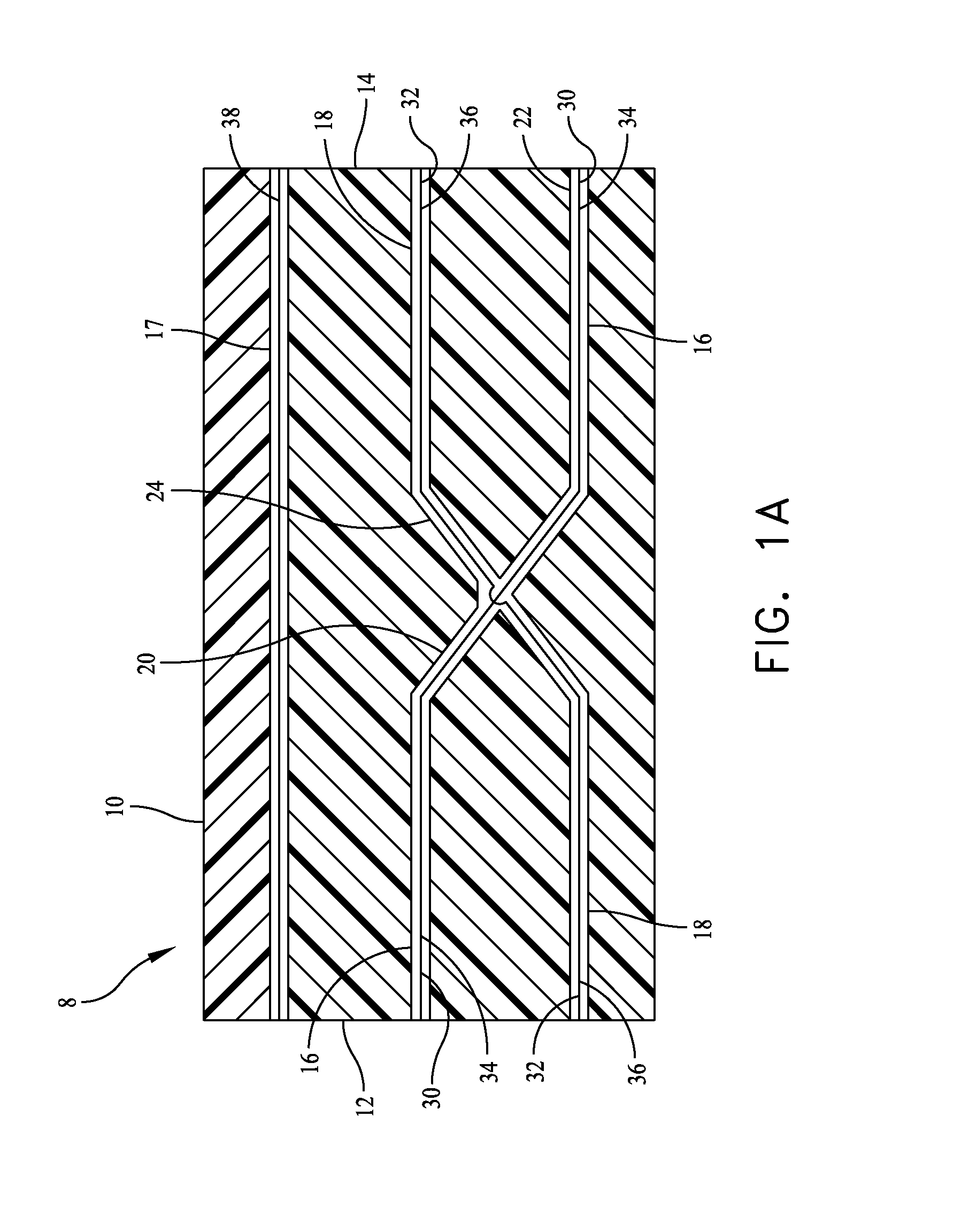
[0037]Referring to FIG. 1, it will be seen that an electrical cable harness 8, suitable for interconnection of components of an assembly for converting solar power to AC electrical power, includes an electrically insulative housing 10 having first and second ends 12, 14. A plurality of passageways 16, 18 extend through the housing 10 from the first end 12 of the housing 10 to the second end 14 of the housing 10.

[0038]The first passageway 16, between the first and second connector ends 12, 14 of the housing 10, is provided with a first angled portion 20 extending to a portion 22 of the first passageway 16 in alignment with the second passageway 18 and extending to the second end 14 of the housing 10.

[0039]Similarly, the second passageway 18, between the first and second ends 12, 14 of the housing 10, is provided with a second angled portion 24 extending to a portion 26 of the second passageway 18 in alignment with the first passageway 16 and extending to the second end 14 of the hous...


PUM

PropertyMeasurementUnit
voltageaaaaaaaaaa
electrically conductiveaaaaaaaaaa
conductiveaaaaaaaaaa

Abstract

An electrical connector/cable harness includes an electrically insulative housing and first and second passageways extending from a first end of the connector/cable harness to a second end thereof, first and second electrically conductive wires disposed in the passageways, respectively, wherein the passageways and the wires therein reverse their dispositions in the connector/cable harness such that at the second end of the connector/cable harness the two wires are disposed oppositely to their disposition at the first end of the connector/cable harness.

Description

CROSS-REFERENCE TO RELATED APPLICATION[0001]This application claims priority from U.S. Provisional Patent Application No. 61 / 072,226, filed Mar. 28, 2008 in the names of Ruel D. Little and Zachary A. King.BACKGROUND OF THE INVENTION[0002]1. Field of the Invention[0003]The invention relates to assemblies for interconnecting AC generators and AC powered systems, and for converting solar energy to AC electrical power, and to electrical connector and cable harness means for interconnecting components of such assemblies.[0004]2. Description of the Prior Art[0005]Assemblies for converting DC sources of electrical energy, such as solar cells, batteries, and the like, to readily usable AC electrical power are known. However, current systems, particularly in the solar energy area, comprise a variety of components from multiple manufacturers. Such components in the solar energy area include photovoltaic cells, commonly referred to as solar cells, which convert solar energy to DC electrical po...

Claims


Application Information

Patent Timeline
Patent Type & Authority Applications(United States)
IPC IPC(8): H01B7/00H01R33/00H01R13/64
CPCH01L31/05H01R23/27H02S40/36H01R9/226H02S40/32Y02E10/50H01R24/84
Inventor LITTLE, RUEL DAVENPORTKING, ZACHARY ADAM
Owner FTC SOLAR INC
Why Eureka
Try Eureka