Light-emitting device, display device, and method for controlling driving of the light-emitting device

Active Publication Date: 2009-10-01
SOLAS OLED LTD
View PDF10 Cites 18 Cited by
  • Summary
  • Abstract
  • Description
  • Claims
  • Application Information

AI Technical Summary

Benefits of technology

[0010]A further advantage of the present invention is in providing a light-emitting device, a display device, and a method for controlling driving of the light-emitting device that is capable of carrying out driving taking into consideration changes in the characteristics of the light-emitting elements.
[0011]In order to bring about the aforementioned advantages, a light-emitting device of the present invention comprises:
[0014]at least one pixel having a light-emitting element with one end electrically connected to the power supply line and another end set to a prescribed potential, and a first transistor connecting the data line(s) and one end of the ligh

Problems solved by technology

However, the aforementioned display device cannot measure the voltages across the terminals of the organic EL elements and detection of changes in the characteristics of the o

Method used


Image

  • Light-emitting device, display device, and method for controlling driving of the light-emitting device
  • Light-emitting device, display device, and method for controlling driving of the light-emitting device
  • Light-emitting device, display device, and method for controlling driving of the light-emitting device

Examples


first embodiment

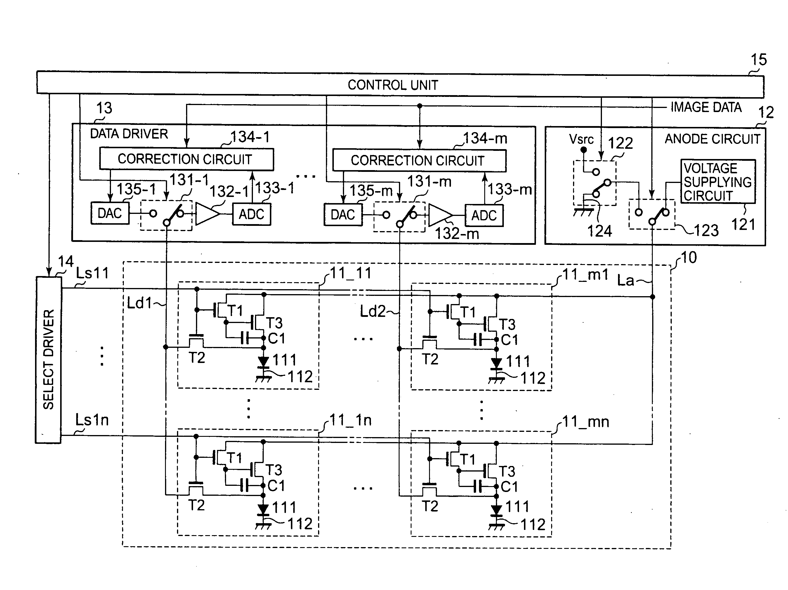
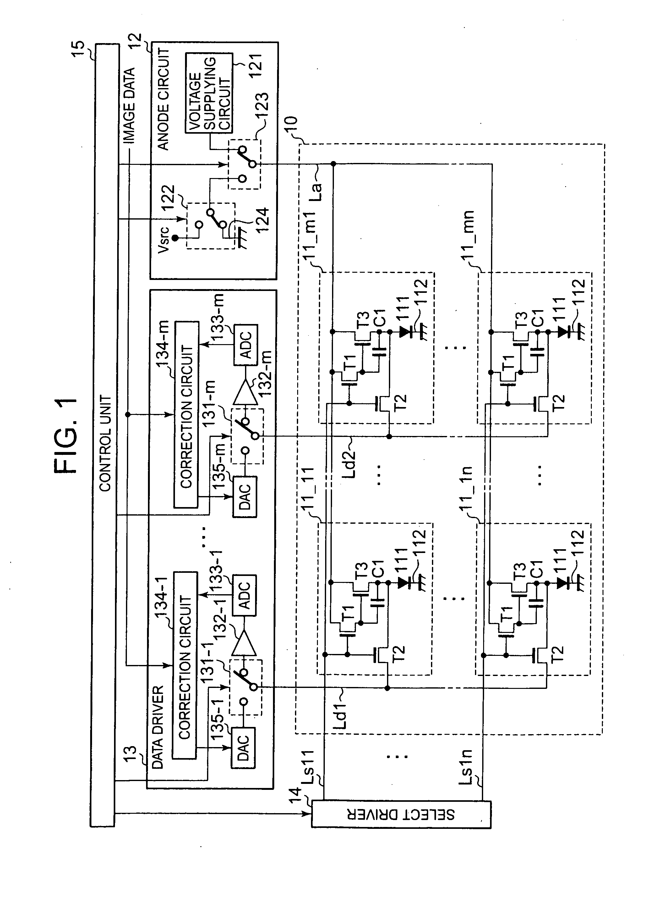
[0131]A configuration for a display device of a first embodiment is shown in FIG. 1.

[0132]A display device of a first embodiment includes a plurality of pixels 11—ij (where i=1 to m, j=1 to n, and m, n; natural numbers), a light-emitting region (light-emitting region) 10 where the plurality of pixels 11—ij are arranged, an anode circuit (a power supply line driving unit) 12, a data driver (data drive unit) 13, a select driver (select driver unit) 14, and a control unit 15.

[0133]Each pixel 11—ij corresponds to one pixel of an image. Each of the pixels 11—ij are arranged in a matrix in row and column directions at a light-emitting region 10. Each pixel 11—ij includes an organic EL element 111 constituting a light-emitting element, and a pixel driver circuit of transistors T1 to T3 and a capacitor (voltage holding unit) C1.

[0134]The organic EL element (Organic Electroluminescent Element) 111 is a light-emitting element that utilizes a phenomenon where light is emitted by the occurrence...

second embodiment

[0241]A display device of a second embodiment measures the voltage of each organic EL element every row.

[0242]In image displaying, current flowing every row is different when the frequency of displaying lateral lines is higher. The values of the voltages VEL are therefore different every row. The display device of the second embodiment therefore measures the voltage VEL every row in order to measure the voltage VEL accurately even in this kind of case.

[0243]The display device of the second embodiment has the same configuration as for the first embodiment shown in FIG. 1.

[0244]Next, an explanation is given of the operation of the display device of the second embodiment.

[0245]In the operation for measuring the voltage VEL, the control unit 15 measures the voltages VEL of the organic EL elements 111 for each pixel 11—ij of each row. As shown in FIG. 9, the control unit 15 controls the switch 123 so that the voltage supplying circuit 121 of the anode circuit 12 and the anode line La are...

third embodiment

[0268]A display device of a third embodiment measures the voltage of each organic EL element of each pixel every pixel.

[0269]For example, in cases such as for an indicator for a digital camera where displaying takes place for a long time, when an organic EL element 111 partially deteriorates, the voltage VEL becomes different every pixel. The display device of the third embodiment therefore measures the voltage VEL every pixel in order to measure the voltage VEL of each organic EL element 111 accurately even in this kind of case.

[0270]A configuration for a display device of the third embodiment is shown in FIG. 10.

[0271]In addition to the first select driver 14 (first select driver unit) of the same configuration as for the first embodiment, the display device of the third embodiment includes a second select driver 16 (second select driver unit). The first select driver 14 is controlled by the control unit 15 so as to put the transistors T1 (third transistor) for each of the pixels ...


PUM


Abstract

A light-emitting device comprises a power supply line, at least one data line, at least one pixel having a light-emitting element with one end electrically connected to the power supply line and another end set to a prescribed potential, and a first transistor connecting the data line(s) and one end of the light-emitting element, a current supplying circuit that outputs a verification current of a preset value, and a data driver unit having voltage measuring circuits that acquire a voltage of the one end of the light-emitting element as the verification voltage when the verification current flows via a current path of the data line and the first transistor of the pixel, from the one end of the light-emitting element to the other end from the current supplying circuit via the power supply line.

Description

BACKGROUND OF THE INVENTION[0001]1. Field of the Invention[0002]The present invention relates to a light-emitting device, a display device, and a method for controlling driving of the light-emitting device, and particularly relates to a light-emitting device including light-emitting elements at pixels, a display device equipped with this light-emitting device, and a method for controlling driving of the light-emitting device.[0003]2. Description of the Related Art[0004]In the related art, light-emitting devices having light-emitting elements such as organic ELs, inorganic ELs, or LEDs as light-emitting elements for pixels, with each of the pixels then being arranged in a column or in a matrix and the light-emitting elements of each pixel then emitting light, and light-emitting element type displays (display devices) that carry out display using such light-emitting devices are well-known.[0005]Active matrix driving method light-emitting element displays in particular are superior fro...

Claims


Application Information

Patent Timeline
IPC IPC(8): G06F3/038G09G3/32
CPCG09G3/325G09G3/3266G09G3/3283G09G2300/0842G09G2330/021G09G2320/0295G09G2320/043G09G2320/045G09G2300/0866G09G3/20G09G3/30
Inventor MIZUTANI, YASUSHIMORIMOTO, KAZUNORIOZAKI, TSUYOSHI
Owner SOLAS OLED LTD
Why Eureka
Try Eureka