Camera System And Camera Body Composing The Same

Inactive Publication Date: 2009-10-01
PANASONIC CORP
View PDF7 Cites 15 Cited by
  • Summary
  • Abstract
  • Description
  • Claims
  • Application Information

AI Technical Summary

Benefits of technology

[0016]The aforementioned camera system having no movable mirror between an optical system and an imaging element and enabling determination of picture composition upon imaging a still image by using a moving image displayed on a display un

Problems solved by technology

When an erroneous operation in this situation is performed such as carelessly detaching an interchangeable lens from a camera body, a problem is caused that the film is exposed since the film loaded in the camera is uncovered.
A digital single-lens reflex camera that has a movable mirror and that electronically records an image using an imaging element such as a CMOS image sensor has the same problem.
Specifically, when light incident from the outside exposes the imag

Method used


Image

  • Camera System And Camera Body Composing The Same
  • Camera System And Camera Body Composing The Same
  • Camera System And Camera Body Composing The Same

Examples


first embodiment

1. Configuration

[0022]1-1. Configuration of Camera System

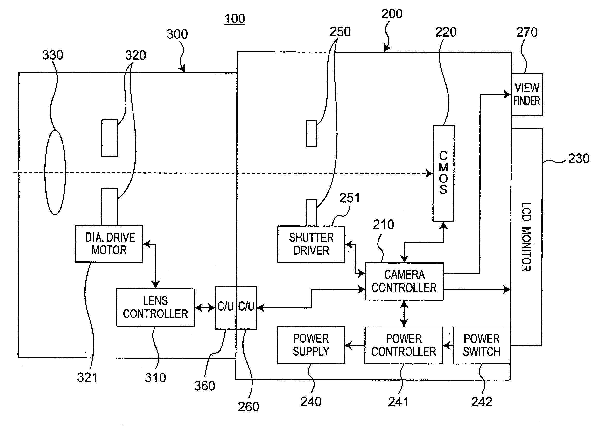
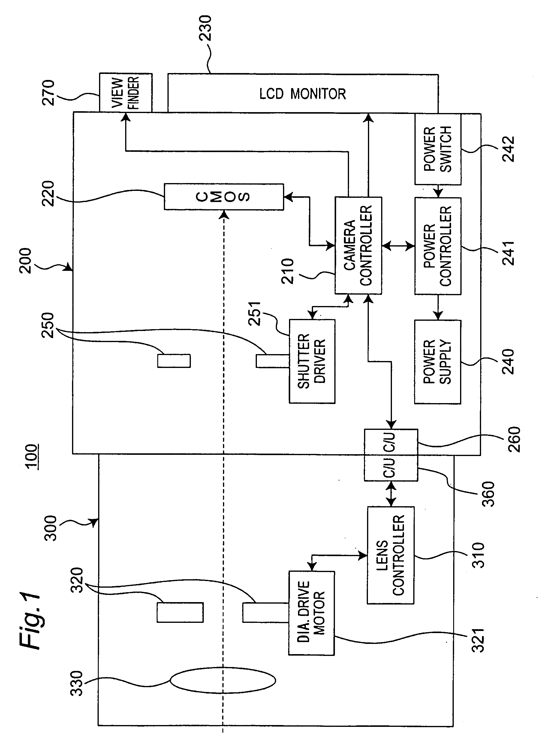
[0023]FIG. 1 is a block diagram showing a configuration of a camera system according to a first embodiment. A camera system 100 includes a camera body 200 and an interchangeable lens 300 mountable to the camera body 200.[0024]1-2. Configuration of Camera Body

[0025]The camera body 200 includes a CMOS image sensor 220, a liquid crystal display (LCD) monitor 230, a power controller 241, a shutter driver 251, an electronic viewfinder 270, and a camera controller 210 for controlling these components. Note that the camera body 200 may include a memory card slot, a strobe, a DRAM, and soon in addition to the components shown in FIG. 1.

[0026]The CMOS image sensor 220 captures a subject image formed by the interchangeable lens 300 to generate image data. The image data generated by the CMOS image sensor 220 is subjected to processes, such as a YC conversion process, an electronic zoom process, and a compression process, in the camera c...

second embodiment

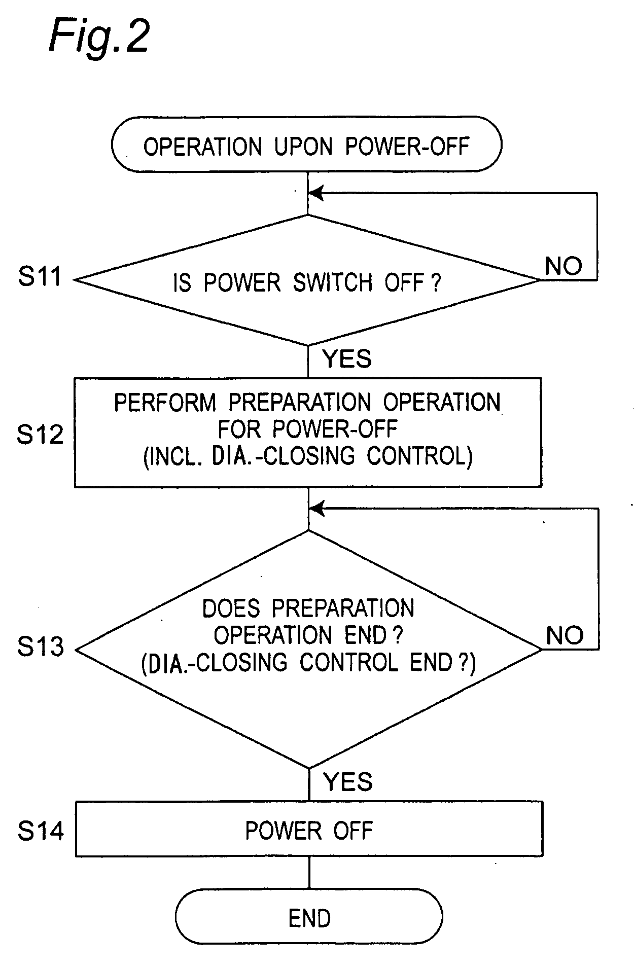
[0057]FIG. 4 is a block diagram showing a configuration of a camera system according to a second embodiment. As shown in FIG. 4, a camera body 200 further includes a barrier mechanism 280 and a barrier drive motor 281 for driving the barrier mechanism 280. Inthe first embodiment, the aperture of the diaphragm 320 is narrowed upon power-off. In the present embodiment, the camera controller 210 controls the barrier drive motor 281 to close the barrier mechanism 280 when the power is turned off. Then, after the barrier mechanism 280 is closed, the camera controller 210 notifies a power controller 241 that power-off is enabled. When receiving the notification from the camera controller 210 that power-off is enabled, the power controller 241 stops supply of power from a power supply 240.

[0058]The barrier mechanism 280 is provided in the middle of an optical path extending from an optical system in the interchangeable lens 300 to the CMOS image sensor 220, and is a mechanically openable a...


PUM


Abstract

A camera system includes a controller operable to control operations of a camera body and an interchangeable lens. When supply of power from a power supply of the camera body is requested to be stopped, the controller performs control to adjust an aperture of the diaphragm such that an amount of light passing through the diaphragm is no greater than a predetermined value, and thereafter, to stop the supply of power.

Description

BACKGROUND[0001]1. Technical Field[0002]The technical field relates to a lens-interchangeable camera system and more particularly to control of the camera system upon power-off.[0003]2. Related Art[0004]A single-lens reflex camera to which an interchangeable lens is mountable has a movable mirror in a camera body thereof. Normally, the movable mirror is located in an observation position and light incident to the interchangeable lens is reflected by the movable mirror and the reflected light is further guided to a viewfinder through a prism provided at an upper part of the camera body. An operator can check a shooting target from the viewfinder. Upon taking a picture, the movable mirror momentarily is flipped up to move to a shooting position. Thus, the incident light through the interchangeable lens is guided to film loaded in the camera body and exposes the film so that an image can be recorded.[0005]In such a single-lens reflex camera, when a power switch is turned off with a mov...

Claims


Application Information

Patent Timeline
IPC IPC(8): H04N5/225H04N5/235
CPCH04N5/23209H04N2101/00H04N5/23241H04N23/663H04N23/651
Inventor UEDANAKAJIMA, HIDEKAZUAOKI, TAIZO
Owner PANASONIC CORP
Why Eureka
Try Eureka