This helps you quickly interpret patents by identifying the three key elements:
Problems solved by technology
Method used
Benefits of technology
Benefits of technology
[0040]According to the present invention, it is possible to correct density non-uniformities caused by variations in t
Problems solved by technology
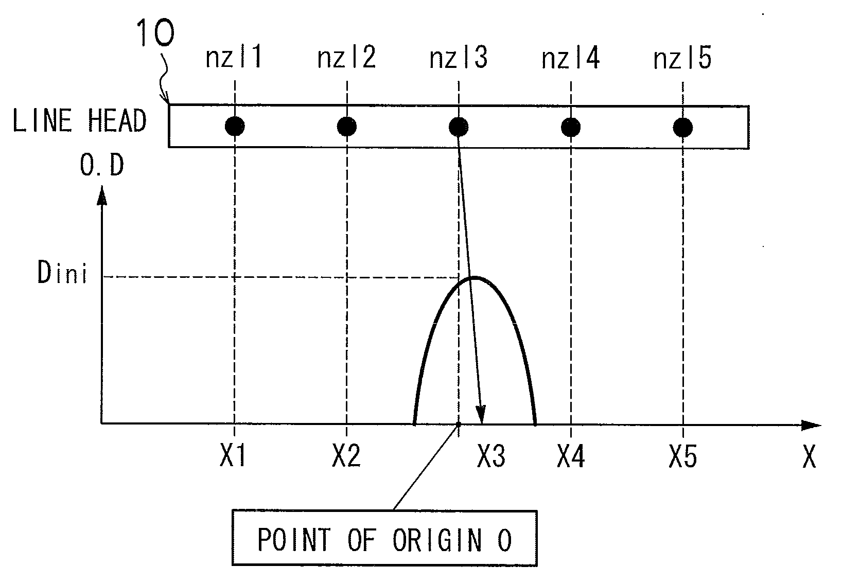
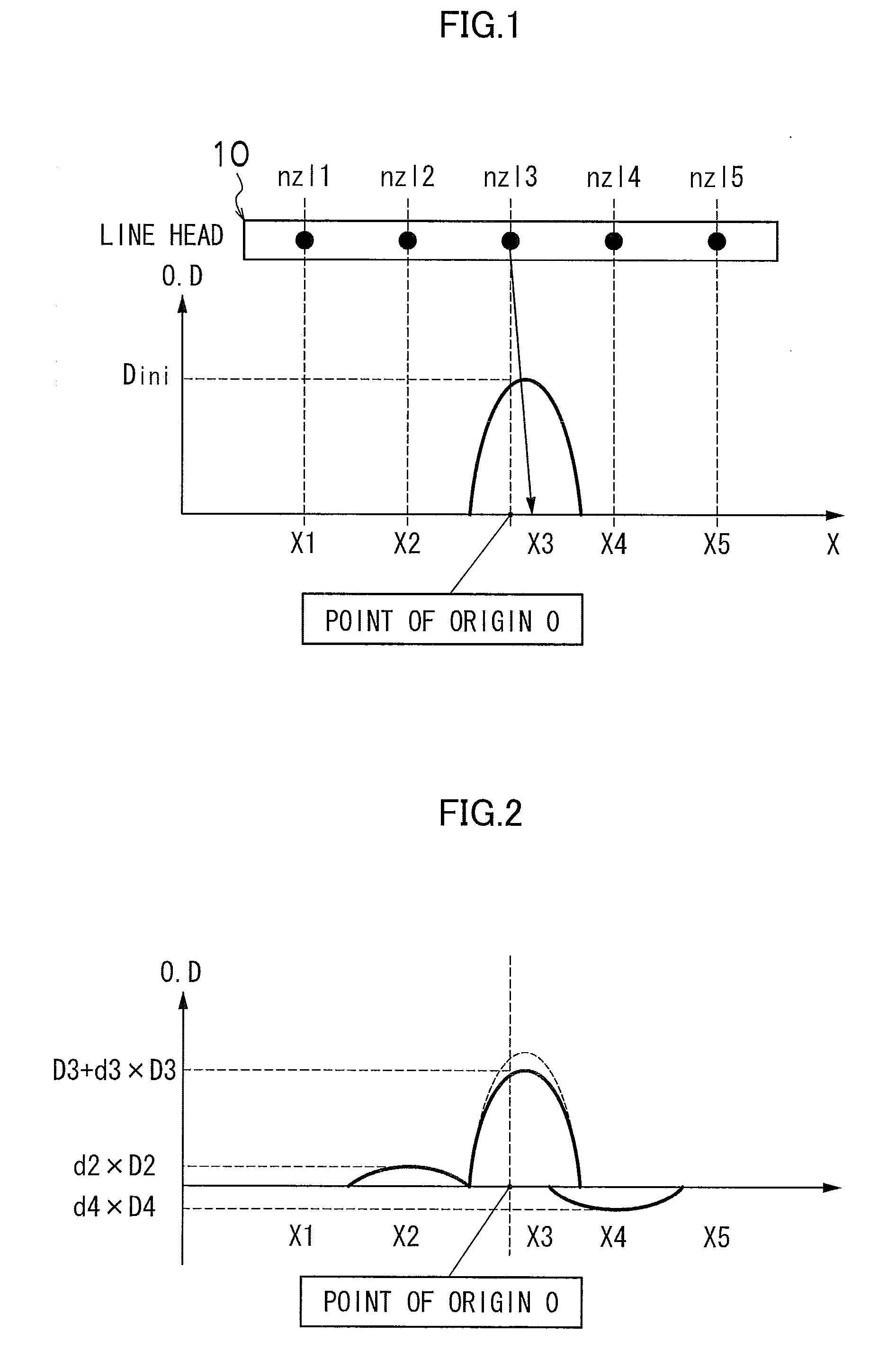
In this type of image recording apparatus, problems of image quality are liable to arise due to the occurrence of density variations (density non-uniformities) in the recorded image caused by variations in the ejection characteristics of the nozzles. FIG. 21 is an illustrative diagram showing a schematic view of examples of variations in the ejection characteristics of the nozzles, and density variations appearing in recording results.
In the case of a serial (shuttle) scanning type of image recording apparatus, which performs image recording by driving a recording head to scan a plurality of times over the prescribed print region, it is possible to avoid density non-uniformities by means of a commonly known multi-pass printing method, but in the case of a single pass system (line head system) which records images by means of a single scanning action, it is difficult to avoid density non-uniformities.
However, with the technolog
Method used
Image
Click on the blue label to locate the original text in one second.
Reading with bidirectional positioning of images and text.
Examples
embodiment 1
Processing Flow from Image Data Correction Processing to Image Output: Embodiment 1
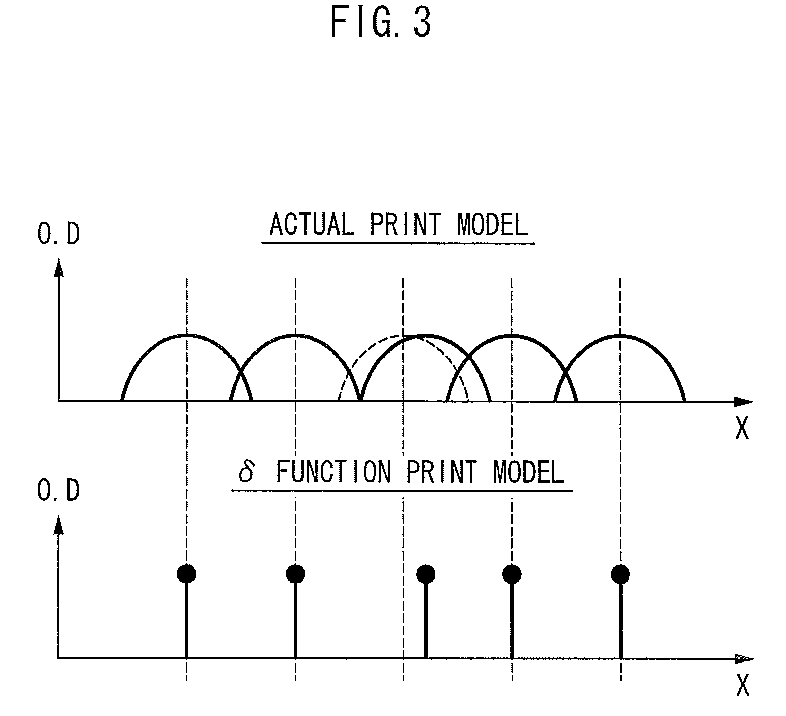
[0115]FIGS. 8A, 8B and 8C show a flowchart of a detailed processing procedure for outputting an image according to a first embodiment. When this processing is started, firstly, the upper limit value Dmax and the lower limit value Dmin of the output image density are specified and set in accordance with the capability of the recording head of the inkjet recording apparatus (step S110). Thereupon, the density correction values d(N) for the respective nozzles (total number of nozzles=N) are calculated from the droplet depositing position error data, using the method described with reference to FIGS. 1 to 3 (the method described in U.S. Pat. No. 7,484,824) (step S112).
[0116]The image data is then corrected using the correction data determined at step S112 (step S114). In other words, taking the X direction as the direction parallel to the nozzle row (the main scanning direction in a single-pass method usi...
embodiment 2
Processing Flow from Image Data Correction Processing to Image Output: Embodiment 2
[0132]FIGS. 10A, 10B and 10C show a flowchart of a detailed processing procedure for outputting an image according to a second embodiment. When this processing is started, firstly, the upper limit value of the image density is set as Dmax and the lower limit value of the image density is set as Dmin (step S210). Thereupon, density correction values dtemp(N) for the respective nozzles (total number of nozzles=N) are calculated from the droplet depositing position error data, using the correction method described in U.S. Pat. No. 7,484,824 (step S212).
[0133]The stored density correction values d(N,Dmax) for the respective image densities are then cleared (to 0) (step S214). Then, the calculation variable parameter D is set to “Dmin” (step S216), and the first nozzle number is set in the x value loop counter (step S218).
[0134]Next, it is judged whether or not the density correction value “D×dtemp(x)” tha...
modified embodiment 1
[0230]It is also possible to adopt a mode in which all or a portion of the functions carried out by the depositing error measurement calculation unit 172A, the density correction coefficient calculation unit 172B, the density data generation unit 180A and the correction processing unit 180B, which are described in FIG. 16, are installed in the host computer 186.
PUM
Abstract
The image recording apparatus records an image on a recording medium. The image recording apparatus includes: a recording head which has a plurality of recording elements; a conveyance device which conveys at least one of the recording head and the recording medium so that the recording head and the recording medium move relatively to each other; a characteristics information acquisition device which acquires characteristics information that indicates recording characteristics of the respective recording elements; a correction calculation device which corrects image data corresponding to the respective recording elements by using at least recording point positional deviation information within the acquired characteristics information, and generates image data that suppresses a non-uniformity streak occurring in an output image due to the recording characteristics; a nearest recording point specifying device which specifies, in a case where an image density value indicated by the image data corrected by the correction calculation device is out of an output image density range of the recording head, a second recording element concerning a recording position nearest to a recording position of a first recording element corresponding to first image data that is out of the output image density range; a sum density calculation device which calculates a sum density of the first image data and second image data, the first image data corresponding to the first recording element, the second image data corresponding to the specified second recording element and having been corrected by the correction calculation device for the image data corresponding to the specified second recording element; an image data modification device which preserves the sum density calculated by the sum density calculation device, while distributing the sum density to respective image data corresponding to the first recording element and the second recording element, at values within the output density range; and a drive control device which controls driving of the recording head in accordance with the image data corrected by the correction calculation device and the image data modified by the image data modification device.
Description
BACKGROUND OF THE INVENTION[0001]1. Field of the Invention[0002]The present invention relates to an image recording apparatus and an image recording method, and more particularly to image correction processing technology which is suitable for correcting density variations caused by variation in characteristics among a plurality of recording elements in a recording head.[0003]2. Description of the Related Art[0004]An image recording apparatus (inkjet printer) has been used which includes an inkjet type of recording head having a plurality of ink ejection ports (nozzles). In this type of image recording apparatus, problems of image quality are liable to arise due to the occurrence of density variations (density non-uniformities) in the recorded image caused by variations in the ejection characteristics of the nozzles. FIG. 21 is an illustrative diagram showing a schematic view of examples of variations in the ejection characteristics of the nozzles, and density variations appearing in...
Claims
Application Information
Patent Timeline
Application Date:The date an application was filed.
Publication Date:The date a patent or application was officially published.
First Publication Date:The earliest publication date of a patent with the same application number.
Issue Date:Publication date of the patent grant document.
PCT Entry Date:The Entry date of PCT National Phase.
Estimated Expiry Date:The statutory expiry date of a patent right according to the Patent Law, and it is the longest term of protection that the patent right can achieve without the termination of the patent right due to other reasons(Term extension factor has been taken into account ).
Invalid Date:Actual expiry date is based on effective date or publication date of legal transaction data of invalid patent.

