
Image recording apparatus and method

a technology of image recording and recording method, which is applied in the direction of instruments, digital computers, computing, etc., can solve the problems of difficult to avoid density non-uniformities, inability to achieve suitable avoidance processing, and prone to image quality problems, etc., to achieve accurate density non-uniformities, high quality, and high accuracy

Inactive Publication Date: 2009-10-01
FUJIFILM CORP
View PDF4 Cites 3 Cited by
  • Summary
  • Abstract
  • Description
  • Claims
  • Application Information

AI Technical Summary

Benefits of technology

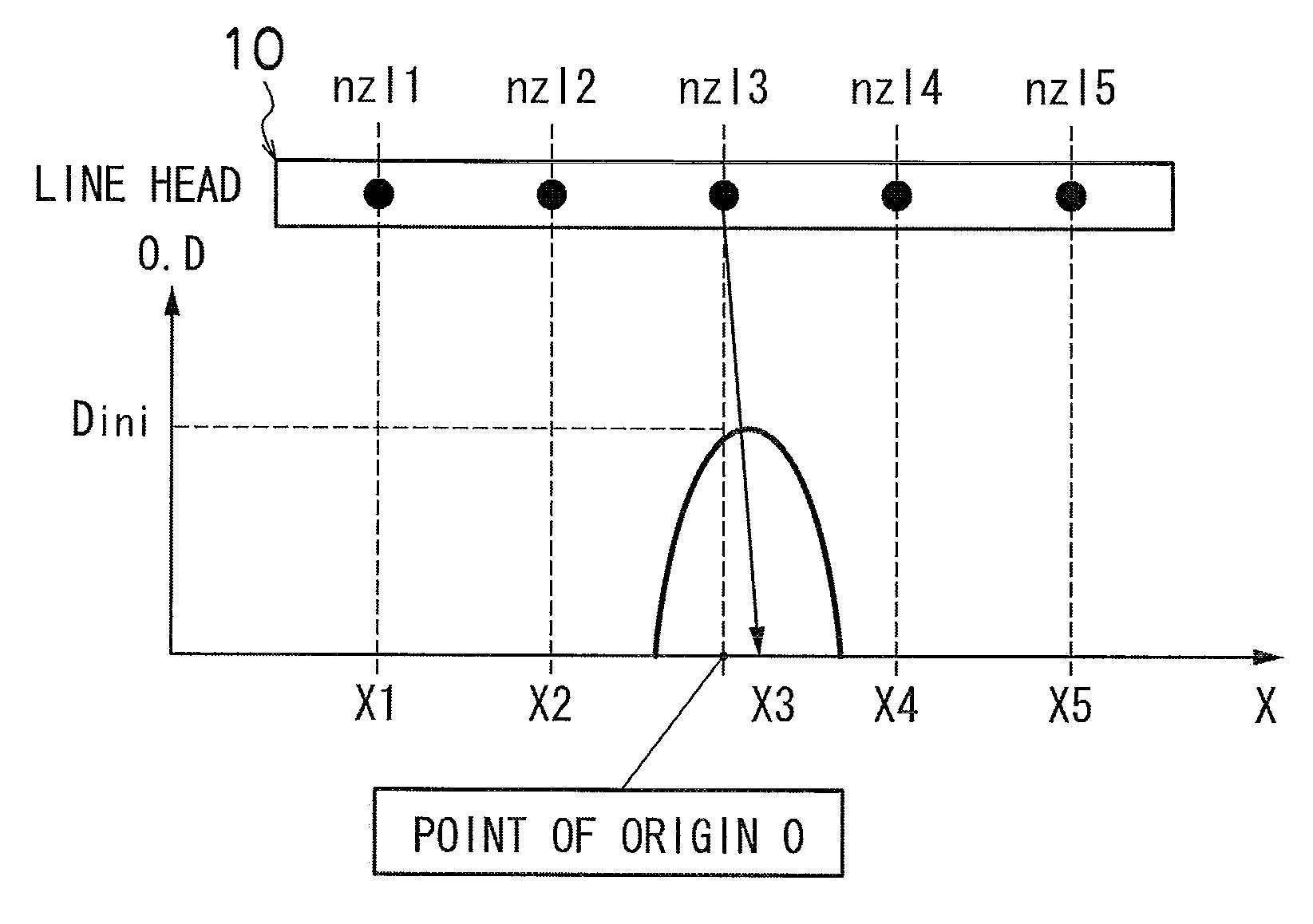
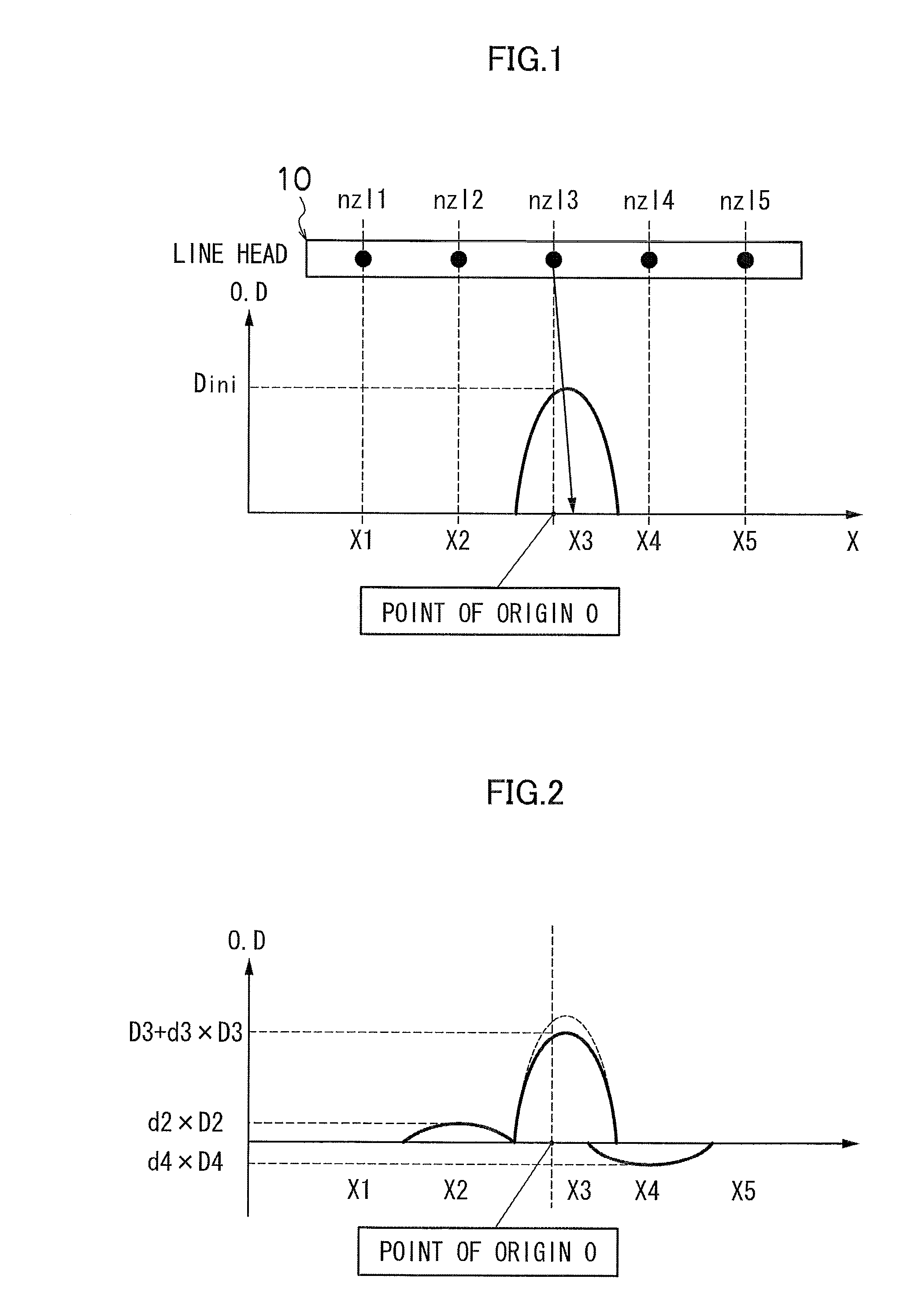
[0012]The present invention has been contrived in view of these circumstances, an object thereof being to eliminate the problems described above by providing an image recording apparatus and an image recording method whereby highly accurate density correction (suppression of banding) can be achieved, and a computer readable medium having embodied thereon an image processing program which is valuable in correction processing of the apparatus and method.
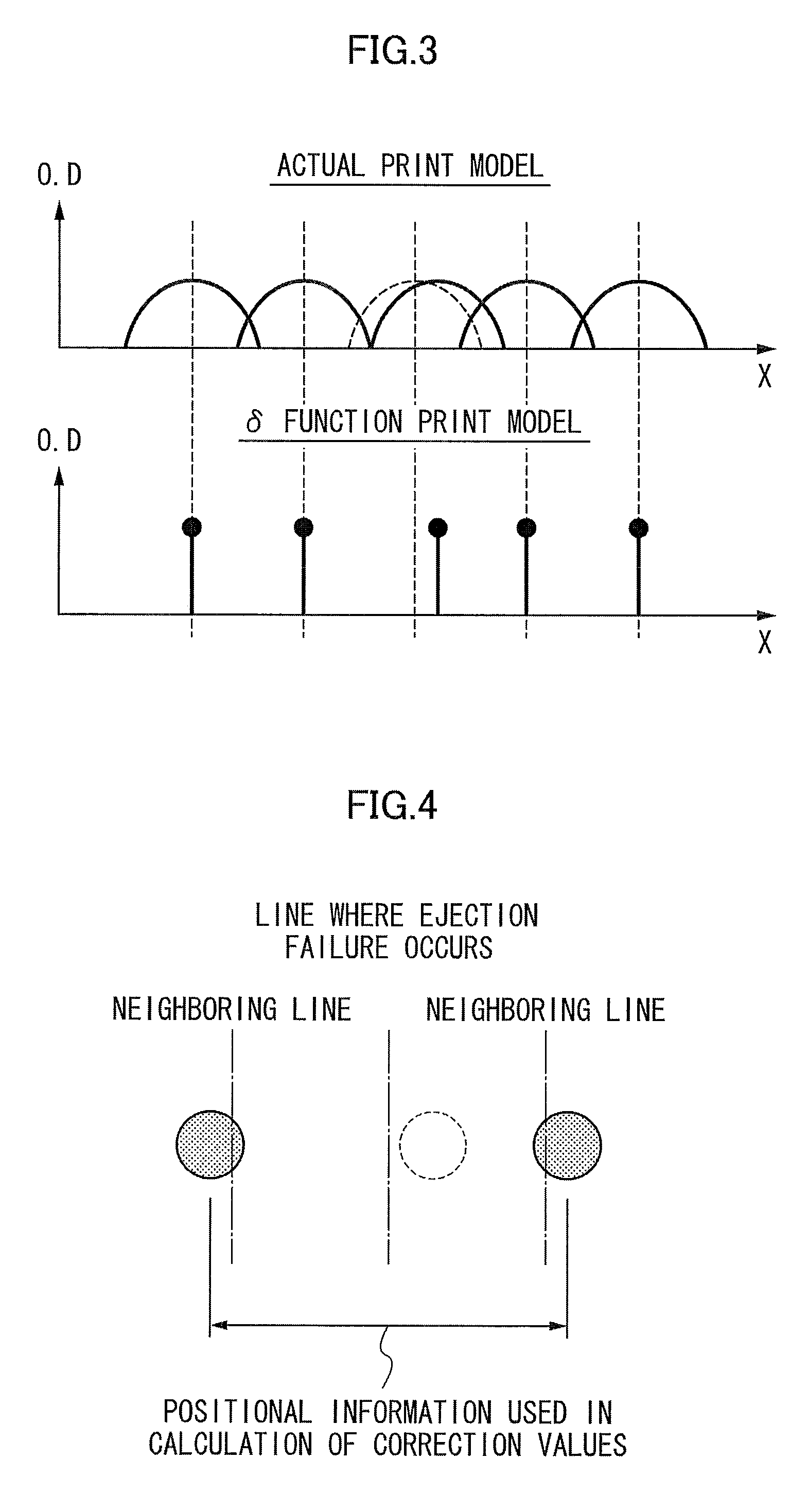
[0014]According to this aspect of the present invention, the characteristics information of the recording elements includes at least the recording point positional information and the recording-incapable element information, and the recording point positional information that is to be used in calculating the correction values is determined (selected) on the basis of the recording-incapable element information. Thus, the positional information used to calculate the correction values is decided appropriately, in accordance with the state of occurrence of recording elements that are incapable of recording, and therefore it is possible to achieve good image correction even in the event of recording-incapable recording elements occurring.
[0026]Irregularities in the density of a recorded image (density non-uniformities) can be represented by the intensity of the spatial frequency characteristics (power spectrum), and the visibility of a density non-uniformity can be evaluated by means of the low-frequency component of the power spectrum. Since the density correction coefficients are specified by using conditions under which the differential coefficient at the frequency origin point (f=0) of the power spectrum after correction using the density correction data becomes substantially zero, then the intensity of the power spectrum becomes a minimum at the frequency origin point and the power spectrum restricted to a low value in the vicinity of the origin (in other words, in the low-frequency region). Accordingly, highly accurate correction of non-uniformity can be achieved.
[0028]By calculating the correction values without using the recording point positional information of the recording-incapable recording elements, it is possible to carry out suitable image correction by using the recording point positional information for adjacent points on either side of the position where the element is not capable of recording.
[0033]According to the present invention, it is possible to correct density non-uniformities caused by variations in the recording characteristics of recording elements, with high accuracy, and hence images of high quality can be formed.

Problems solved by technology

In this type of image recording apparatus, problems of image quality are liable to arise due to the occurrence of density variations (density non-uniformities) in the recorded image caused by variations in the ejection characteristics of the nozzles. FIG. 24 is an illustrative diagram showing a schematic view of examples of variations in the ejection characteristics of the nozzles, and density variations appearing in recording results.
In the case of a serial (shuttle) scanning type of image recording apparatus, which performs image recording by driving a recording head to scan a plurality of times over the prescribed print region, it is possible to avoid density non-uniformities by means of a commonly known multi-pass printing method, but in the case of a single pass system (line head system) which records images by means of a single scanning action, it is difficult to avoid density non-uniformities.
However, with the technology described in Japanese Patent Application Publication No. 2007-125877, there is a problem in that suitable avoidance processing is not possible in cases where a line where banding occurs relates to a nozzle suffering ejection failure.

Method used


Image

  • Image recording apparatus and method
  • Image recording apparatus and method
  • Image recording apparatus and method

Examples


modified embodiment 1

[0243]It is also possible to adopt a mode in which all or a portion of the functions carried out by the depositing error measurement calculation unit 172A, the density correction coefficient calculation unit 172B, the density data generation unit 180A and the correction processing unit 180B, which are described in FIG. 23, are installed in the host computer 186.

modified embodiment 2

[0244]FIGS. 18 to 23 show the composition where a test pattern is read in by a print determination unit 124 which is provided in an inkjet recording apparatus 110, and a calculation processing function for obtaining deposition error data and a calculation processing function for determining density correction coefficients are incorporated into the system controller (reference numeral 172 in FIG. 23) and / or the print controller (reference numeral 180) of the inkjet recording apparatus 110, in such a manner that the calculation processing is carried out inside the inkjet recording apparatus 110. However, it is also possible to achieve these functions by means of an image reading apparatus which is a device for reading in a test pattern. Moreover, it is also possible to perform these functions by means of an apparatus that is external to the printer so that the image data obtained from the image reading apparatus is processed.

[0245]For example, it is also possible to use a flat-bed sca...

modified embodiment 3

[0246]In the respective embodiments described above, an inkjet recording apparatus using a page-wide full line type head having a nozzle row of a length corresponding to the entire width of the recording medium was described, but the scope of application of the present invention is not limited to this, and beneficial corrective effects can also be obtained in respect of banding non-uniformities in an inkjet recording apparatus which performs image recording by means of a plurality of head scanning actions which move a short recording head, such as a serial head (shuttle scanning head), or the like.

[0247]In the embodiment described above, the inkjet recording apparatus is described as one example of an image forming apparatus, but the range of application of the present invention is not limited to this. It is also possible to apply the present invention to image recording apparatuses employing various types dot recording methods, apart from an inkjet apparatus, such as a thermal tran...


PUM


Abstract

The image recording apparatus records an image on a recording medium. The image recording apparatus includes: a recording head which has a plurality of recording elements; a conveyance device which conveys at least one of the recording head and the recording medium so that the recording head and the recording medium move relatively to each other; a characteristics information acquisition device which acquires characteristics information that indicates recording characteristics of the respective recording elements, the characteristics information including recording point positional information and recording-incapable element information; an information selection device which selects the recording point positional information to be used in calculation of correction values for use in generating image data that suppresses density non-uniformity caused by the recording characteristics in accordance with the recording-incapable element information; a correction value calculation device which calculates the correction values from the recording point positional information selected by the information selection device; a correction processing device which corrects the image data by using the correction values obtained by the correction value calculation device; and a drive control device which controls driving of the recording head in accordance with the image data corrected by the correction processing device.

Description

BACKGROUND OF THE INVENTION[0001]1. Field of the Invention[0002]The present invention relates to an image recording apparatus and an image recording method, and more particularly to image correction processing technology which is suitable for correcting density variations caused by variation in characteristics among a plurality of recording elements in a recording head having the recording elements.[0003]2. Description of the Related Art[0004]An image recording apparatus (inkjet printer) has been used which includes an inkjet type of recording head having a plurality of ink ejection ports (nozzles). In this type of image recording apparatus, problems of image quality are liable to arise due to the occurrence of density variations (density non-uniformities) in the recorded image caused by variations in the ejection characteristics of the nozzles. FIG. 24 is an illustrative diagram showing a schematic view of examples of variations in the ejection characteristics of the nozzles, and d...

Claims


Application Information

Patent Timeline
Patent Type & Authority Applications(United States)
IPC IPC(8): H04N1/60
CPCH04N1/4015
Inventor SASAYAMA, HIROYUKI
Owner FUJIFILM CORP
Learn More