Radio communication base station device

a radio communication and base station technology, applied in the direction of substation equipment, electrical equipment, wireless commuication services, etc., can solve the problems of wasteful use of radio resources, inability to perform operator-specific or ue-specific settings, etc., and achieve the effect of reducing the size of messages in call connection

Inactive Publication Date: 2009-10-01
SOVEREIGN PEAK VENTURES LLC
View PDF4 Cites 54 Cited by
  • Summary
  • Abstract
  • Description
  • Claims
  • Application Information

AI Technical Summary

Benefits of technology

[0020]According to the present invention, it is possible to reduce the size of messages in call connection.

Problems solved by technology

By the way, only the configuration patterns that are defined can be used, and so it is not possible to perform operator-specific setting or UE-specific setting.
However, radio resources are used wastefully taking into account the UE not using the configuration transmitted in broadcast information.

Method used


Image

  • Radio communication base station device
  • Radio communication base station device
  • Radio communication base station device

Examples


embodiment 1

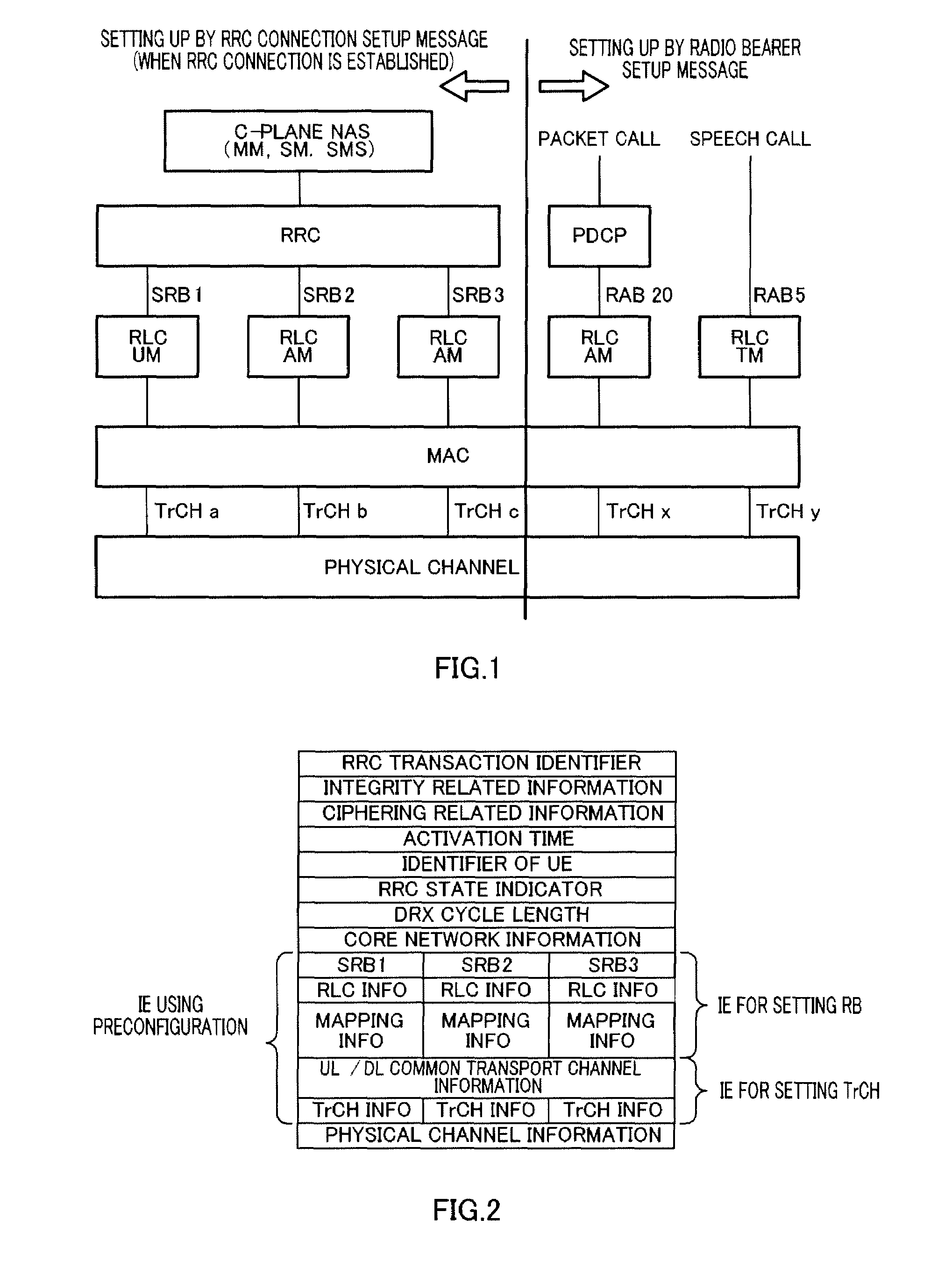
[0062]First, general call connection steps between the radio communication terminal apparatus (“UE,” standing for user equipment) and the radio communication base station apparatus (“node B”) will be explained using FIG. 5. In ST101 in FIG. 5, the UE transmits an RRC connection request message to the node B, and, in ST102, the node B transmits an RRC connection setup message to the UE in response to the RRC connection request message and reports the UE identity, the channel setting for control information, and so on.

[0063]In STl03, the UE performs a channel setting on the UE side according to the details reported in the RRC connection setup message and transmits an RRC connection setup complete message to the node B to report completion of the setting.

[0064]RRC connection establishment is completed through these processing in ST101 to ST103. In this RRC connection establishment, signaling radio bearers (“SRBs”) RB1 (applying an RLC UM mode), RB2 (applying RLC AM for transmission of ...

embodiment 2

[0106]Although a case has been described with Embodiment 1 where the UE holds cell level information of one cell, Embodiment 2 of the present invention will describe a case where the UE holds cell level information of a plurality of cells, as shown in FIG. 19.

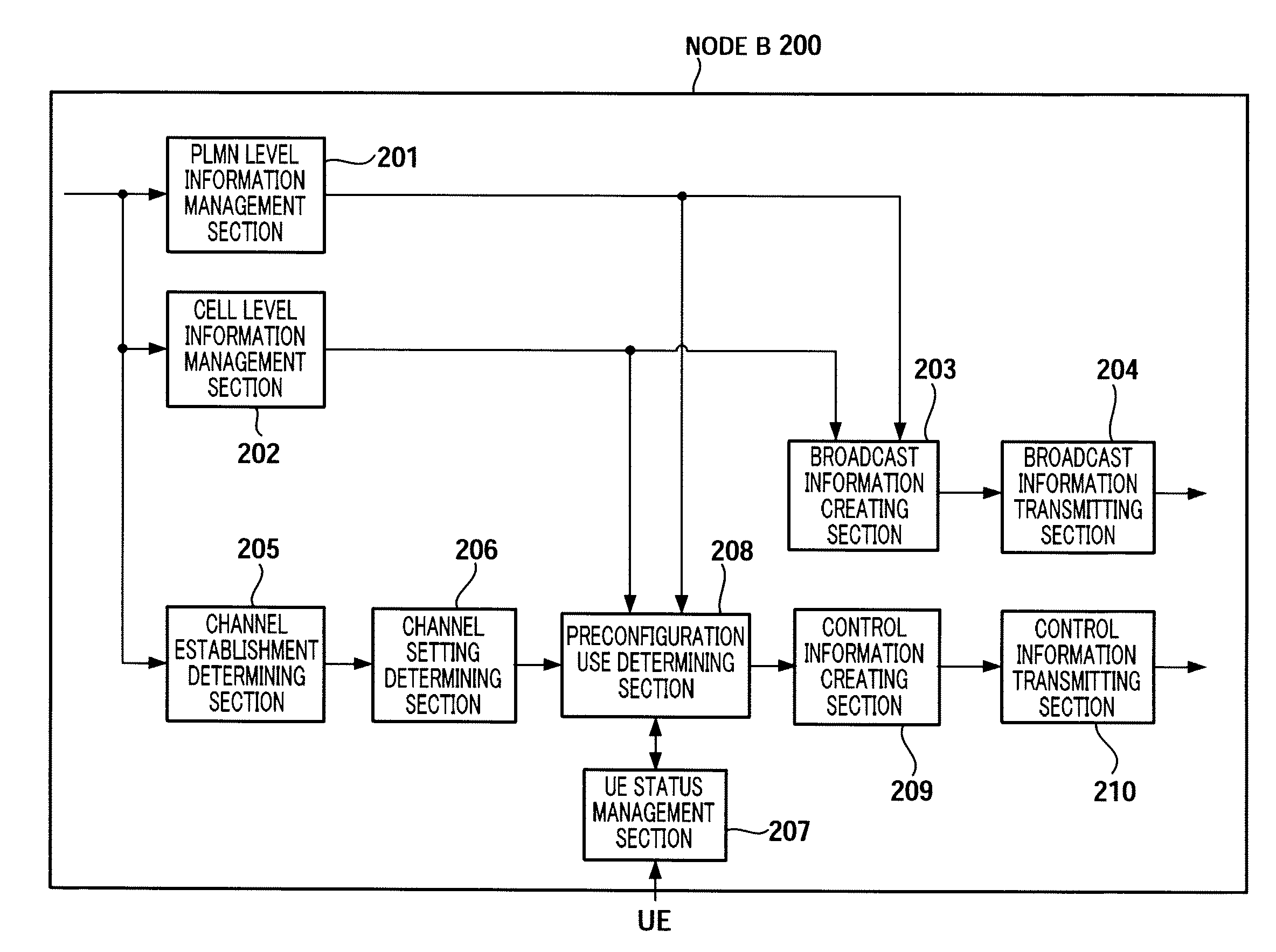
[0107]FIG. 20 is a block diagram showing the configuration of node B 500 according to Embodiment 2 of the present invention. FIG. 20 differs from FIG. 6 in adding neighboring cell status management section 501 and replacing preconfiguration use determining section 208 by preconfiguration use determining section 502.

[0108]In FIG. 20, neighboring cell status management section 501 acquires the status as to whether or not the UE holds the PLMN information and cell level information of neighboring cells from the UE, and manages the acquired status and ID of the UE. Further, upon receiving a UE status report request from preconfiguration use determining section 502, neighboring cell status management section 501 sends back the corre...

embodiment 4

[0134]Embodiment 4 of the present invention focuses on the fact that all data is transmitted in the shared channel in long term evolution (“LTE”), and will describe a case where a cell level is further divided into two types.

[0135]In Embodiment 1, the PLMN level network includes the QoS class, the channel radio access bearer identifier, information about PDCP (header compression), the ciphering or integrity setting, the logical channel setting, the setting / number of retransmissions / reception window size of outer ARQ, the method of sending information for retransmission, a parameter / DRX / DTX interval to implement a DRX / DTX, and the method of reporting a measurement result of the volume of traffic.

[0136]Further, the cell level network includes the available frequency band, the format / TTI / interleave length / coding rate of channel (which are finally determined by a scheduler and of which candidates may not be set up), the transmission method / transmission frequency / quality measurement unit...


PUM


Abstract

Provided is a radio communication base station device capable of reducing a message size in a call connection. In the device, a report information creation unit (203) creates report information by allocating cell level information as Preconfiguration information managed at a cell level and PLMN level information as Preconfiguration information managed at a PLMN level to different transmission units and the created report information is reported from a report information transmission unit (204) to UE. A Preconfiguration use decision unit (208) judges whether the UE which sets a channel can use Preconfiguration. If yes, a control information creation unit (209) includes the corresponding Index in control information and the control information is transmitted from a control information transmission unit (210) to the UE.

Description

TECHNICAL FIELD[0001]The present invention relates to a wireless communication base station apparatus.BACKGROUND ART[0002]Generally, a radio access network (“RAN”) is comprised of the radio network controller (“RNC”) and the node B, where the RNC is connected to the core network (“CN”), which is a switching network through the Iu interface, and the node B is connected to the user equipment (“UE”) through the radio interface.[0003]The protocol architecture of the radio interface is comprised of layer 1 (physical layer), layer 2 (data link layer) and layer 3 (network layer), where a logical channel is defined between layer 3 and layer 2 and a transport channel is defined between layer 2 and layer 1.[0004]Layer 2 is divided into two sub-layers, namely the radio link control (“RLC”) for controlling a radio link and medium access control (“MAC”) for controlling radio resource assignment and so on.[0005]Furthermore, layer 3 is divided into the C-plain for implementing call setting control...

Claims


Application Information

Patent Timeline
Patent Type & Authority Applications(United States)
IPC IPC(8): H04W36/00H04W4/00H04W88/08
CPCH04W88/08H04W48/10
Inventor AOYAMA, TAKAHISA
Owner SOVEREIGN PEAK VENTURES LLC
Why Eureka
Try Eureka