
Method & apparatus for remotely operating a robotic device linked to a communications network

a robotic device and communications network technology, applied in the field of remote robotic control, can solve the problems of no mechanism by which the robot can be remotely controlled, no means to coordinate the robot's movement and audio or video functionality, and the limitation of the control of which multimedia file is downloaded from the remote server to the robotic device,

Inactive Publication Date: 2009-10-01
NORTH END TECH
View PDF13 Cites 100 Cited by
  • Summary
  • Abstract
  • Description
  • Claims
  • Application Information

AI Technical Summary

Benefits of technology

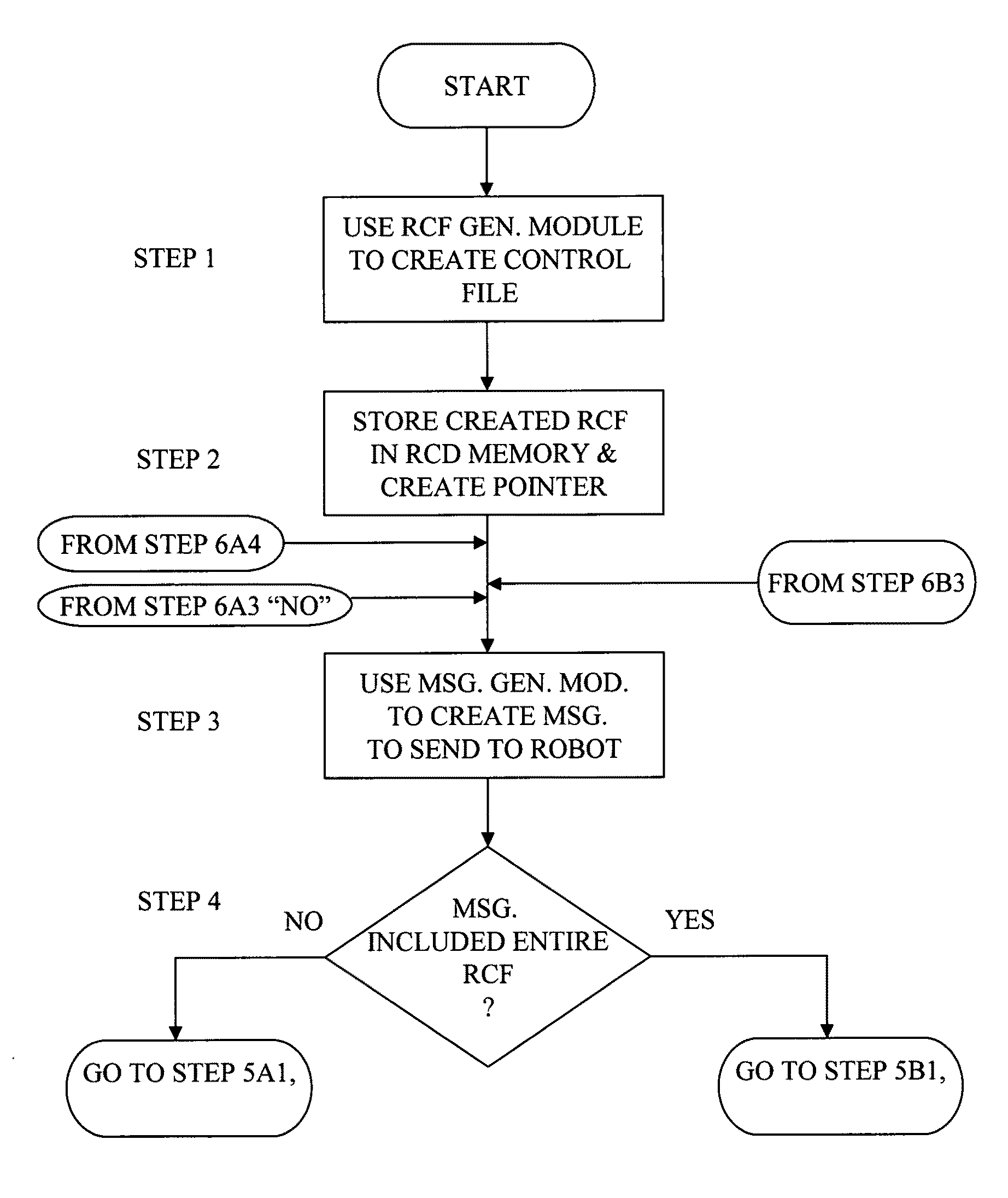
[0007]Another object of the invention is to create simple pre-programmed commands that can be selected from among a plurality of simple, pre-programmed commands which can be easily included in message that are sent over a communications network to a robot causing the robot to perform certain movements and to play or record certain audio, video and multimedia content.

Problems solved by technology

Although the robotic device control methods described above enable the robot movement and the audio and video functions to be controlled from a remote location, there is no means to coordinate the robot's movement and the audio or video functionality.
Furthermore, the remote robotic device motion control mechanism only permits real-time robot control via a manual control device, such as a joy stick and the audio and video control mechanism only permits remote control over real-time audio and video signals.
Although the above application describes a means for coordinating the motion of a robot with a multi-media file, there is no mechanism available by which the robot can be remotely controlled.
Control with respect to which multimedia file is down loaded from the remote server to the robotic device is limited to be local to the robotic device itself.

Method used


Image

  • Method & apparatus for remotely operating a robotic device linked to a communications network
  • Method & apparatus for remotely operating a robotic device linked to a communications network
  • Method & apparatus for remotely operating a robotic device linked to a communications network

Examples


Embodiment Construction

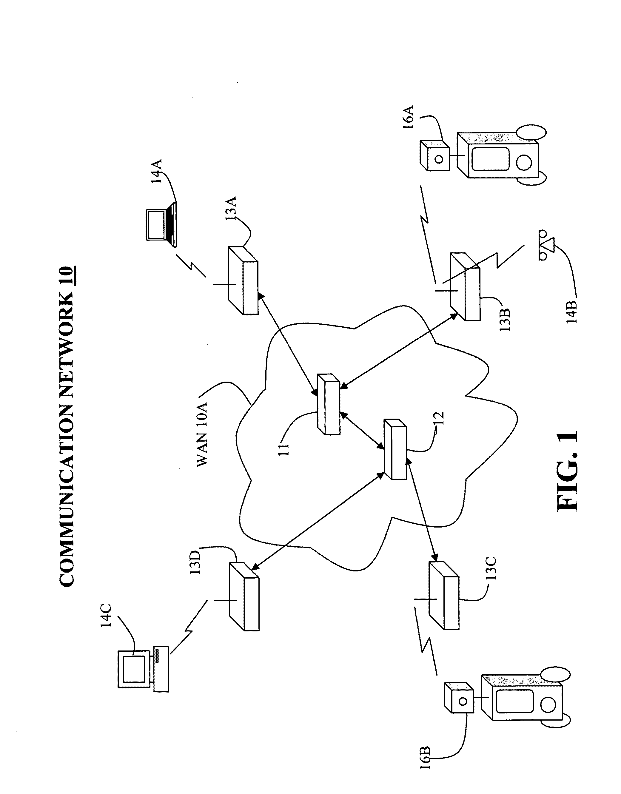
[0018]FIG. 1 is generally illustrative of the network environment in which the invention is implemented. A communications network 10 includes a WAN 10a, which for the purpose of this description can be thought of as being comprised to two network routers 11 and 12, wireless LAN routers (WR) 13a, 13b, 13c and 13d connected to the WAN 10a, remote control devices 14a, 14b, and 14c connected to the four wireless LAN routers, and robotic devices 16a and 16b connected to the wireless LAN routers 13b and 13c respectively. The WAN 10a in the preferred embodiment of the invention is the Internet, but this network can operate according to any one of a number of different wide area network communication protocols. The network routers 11 and 12 can be any type of network communications device capable of receiving packets of information, recognizing at least the destination address contained in the packet and routing or forwarding the packet further along the communications network infrastructur...


PUM


Abstract

A remote control device able to connect to a communications network generates robot control messages are used for the remote control of a robot also able to be connected to the communications network. The remote control device creates a robot control file and an indirect reference to the robot control file which a user can select for inclusion in a robot control message. Once selected, the indirect reference to a robot control file causes the indirectly referenced robot control file to be included in a message generated by the remote control device. The remote control device establishes a communications link with the communications network, and sends the message, with the robot control file, to the robot also connected to the communications network. The robot receives the robot control message and performs at least one action according to the instruction included in the robot control message.

Description

FIELD OF INVENTION[0001]My invention relates generally to the field of remote robotic control and more specifically to the field of remotely controlling the operation of a robotic device over a communications network.BACKGROUND OF THE INVENTION[0002]Robotic devices are currently available that have the capability to, upon command, perform certain movements within their environment, to play and record audio or video or multimedia content from the environment in which they are positioned. Some robotic devices can be remotely controlled either directly by a remote control device proximate to the robotic device or remotely over a network to which both the robotic device and a remote control device are connected. In such a networked arrangement, both the robotic device and remote control device can be in communication with a LAN which can in turn be connected to a WAN. In the event that the robotic device and the remote control device are connected to a LAN, the connection between the ro...

Claims


Application Information

Patent Timeline
IPC IPC(8): G06F19/00
CPCB25J9/1689Y10S901/01B25J9/1602G05B2219/39433
Inventor ROOT, TIMOTHY D.
Owner NORTH END TECH
Learn More