
Vehicle

a technology for vehicles and sensors, applied in the field of vehicles, can solve the problems that the detection of obstacles by the obstacle sensor does not bring the vehicle, and achieve the effect of reliable and convenien

Inactive Publication Date: 2009-10-01
YAMAHA MOTOR CO LTD
View PDF6 Cites 178 Cited by
  • Summary
  • Abstract
  • Description
  • Claims
  • Application Information

AI Technical Summary

Benefits of technology

[0008]In order to overcome the problems described above, preferred embodiments of the present invention provide a reliable and convenient vehicle.
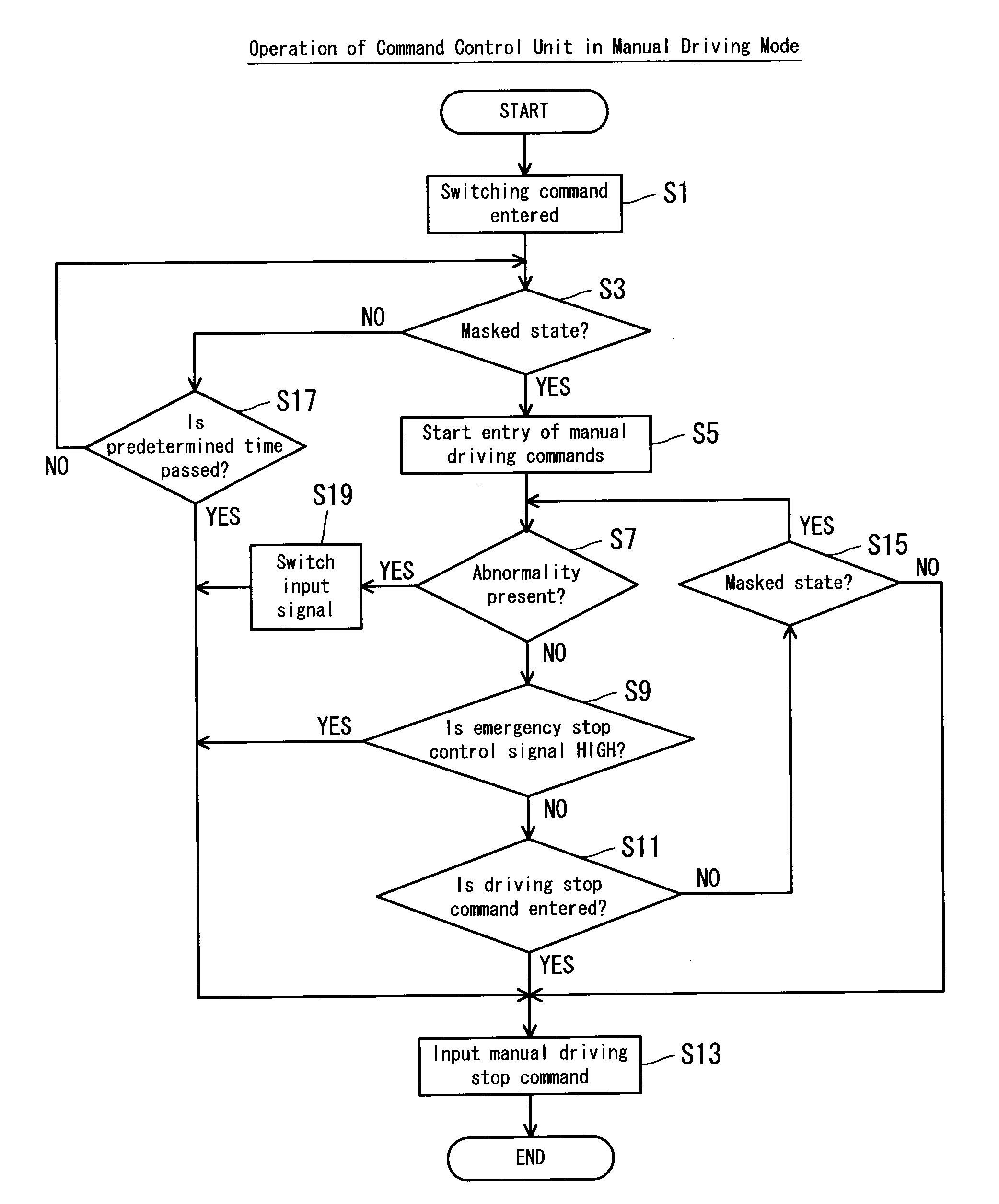
[0010]According to a preferred embodiment of the present invention, when the driving mode is set to the autonomous driving mode by the operation unit, a mask control signal which disables masking of detection signals is inputted from the first controller to the logic circuit. Then, the logic circuit outputs the detection signal from the detector without masking the detection signal, i.e., virtually unchanged, as the emergency stop control signal. By generating the emergency stop control signal virtually directly from the detection signal with a hardware logic circuit, it is possible to generate an emergency stop control signal which corresponds more truly to the detection signal than in a case where the emergency stop control signal is generated by software. In other words, it becomes more reliable that an emergency stop control signal which indicates a need for an emergency stop is outputted when the detector has detected an obstacle, and that an emergency stop control signal which indicates no need for an emergency stop is outputted otherwise. Therefore, it is now possible to bring the vehicle to an emergency stop more reliably upon detection of an obstacle in the autonomous driving mode, and therefore to improve reliability. When the driving mode is set to the manual driving mode by the operation unit, the first controller inputs to the logic circuit a mask control signal which enables the masking of the detection signals. Then, the logic circuit outputs an emergency stop control signal which is made by masking the detection signals. Therefore, even if the detector has detected an obstacle under the manual driving mode, it is now possible to output an emergency stop control signal which indicates no need for an emergency stop from the logic circuit. Therefore, it is possible to drive the vehicle even if the detector has detected an obstacle in the manual driving mode, and this makes it possible to improve convenience.
[0011]Preferably, the vehicle further includes a second controller arranged to input a command to the first controller for outputting the mask control signal which corresponds to the driving mode. With this arrangement, the mask control signal from the first controller is also inputted to the second controller, and the second controller determines whether or not the mask control signal corresponds to the driving mode. In this case, it is possible to monitor the first controller by using the second controller, making it possible to further improve reliability.

Problems solved by technology

However, according to the technique disclosed in JP-A 2006-48614, there is a risk that detection of the obstacle by the obstacle sensor will not bring the vehicle to an emergency stop due to programming errors (bugs) in the emergency stop control, temporary halting of the program execution in the microcomputer, an output error from the microcomputer, etc.
However, this poses a problem of inconvenience since the vehicle will be in the disabled state until the obstacle has been removed.

Method used


Image

  • Vehicle
  • Vehicle
  • Vehicle

Examples


Embodiment Construction

[0025]Hereinafter, preferred embodiments of the present invention will be described with reference to the drawings.

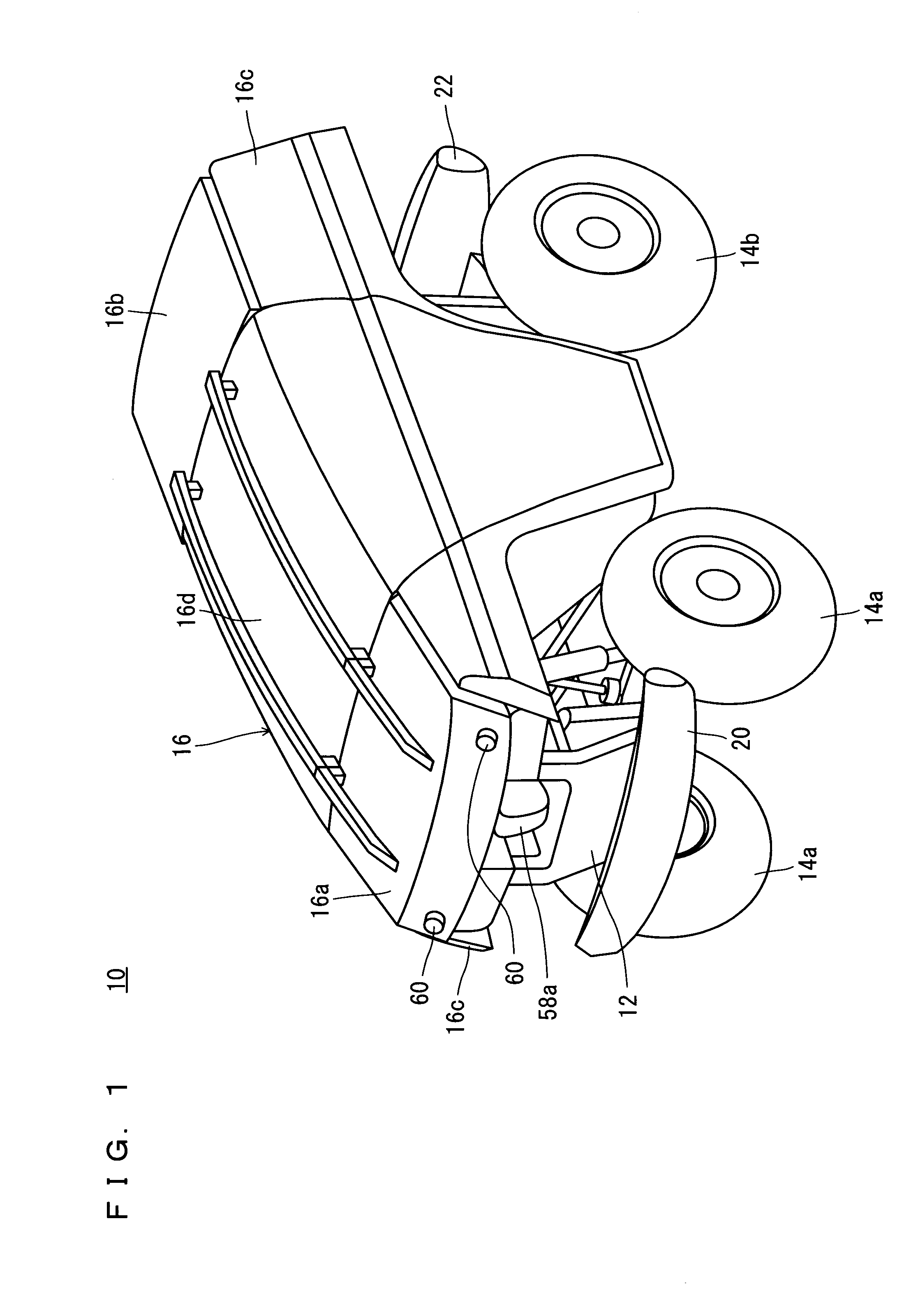
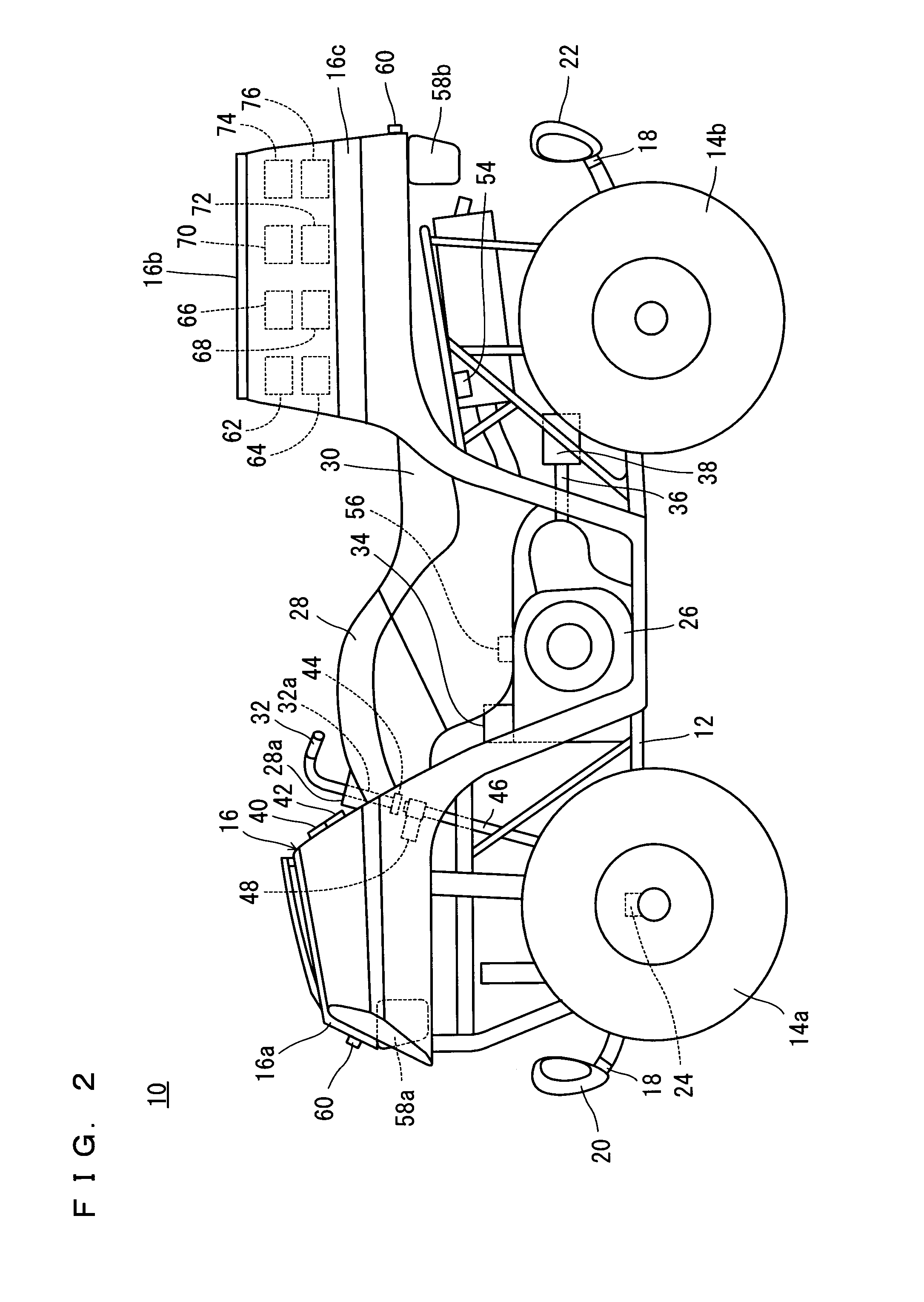
[0026]Referring to FIG. 1 and FIG. 2, a vehicle 10 according to the present preferred embodiment of the present invention preferably is a four-wheeled buggy for driving on a rough terrain, for example, and that is capable of autonomous driving (auto drive) under self-control or manual driving (manual drive) under a human operator's control, for such tasks as farming and surveying. However, the present invention is not limited to such a vehicle and can be applied to any type of vehicle.

[0027]Note here, that the terms right and left, front and rear, as well as up and down as used in the preferred embodiments of the present invention refer to the right and left, front and rear, and up and down respectively, based on a state where a human operator sits on a seat 30 of the vehicle 10, facing toward a vehicle's steering handle 32.

[0028]The vehicle 10 includes a body frame 12 ...


PUM


Abstract

A vehicle includes a button switch and a remote controller for setting an autonomous or manual driving mode, a microcomputer which outputs a mask control signal that corresponds to the driving mode, a command control unit which inputs a command to the microcomputer to output the mask control signal that corresponds to the driving mode, and a forward obstacle sensor and a rearward obstacle sensor which detect an obstacle and output a detection signal. A first logic circuit generates an emergency stop control signal that indicates a need or no need for an emergency stop of the vehicle based on the mask control signal from the microcomputer and the detection signals from the obstacle sensors. An emergency stopping operation of the vehicle is controlled based on the emergency stop control signal from the first logic circuit.

Description

BACKGROUND OF THE INVENTION[0001]1. Field of the Invention[0002]The present invention relates to a vehicle, and more specifically to a vehicle capable of both autonomous driving in which the vehicle runs under self-control and manual driving in which the vehicle runs under a human operator's control.[0003]2. Description of the Related Art[0004]Conventionally, a number of proposals have been made for a vehicle which is capable of autonomous driving and manual driving. In JP-A 2006-48614 for example, inventors of the present invention disclosed a vehicle for autonomous driving which is capable of detecting via an obstacle sensor an obstacle located some distance away from the vehicle along a driving path of the vehicle, actuating a solenoid brake, and disabling an ignition unit. According to the technique in JP-A 2006-48614, it is possible to bring the vehicle to an emergency stop before the vehicle makes contact with the obstacle on the driving path during autonomous driving.[0005]Su...

Claims


Application Information

Patent Timeline
IPC IPC(8): G08G1/16G05D1/00B60W10/04B60W10/06B60W10/18B60W10/184B60W30/09G05D1/02
CPCG05D1/0061
Inventor KAMIYA, TSUYOSHI
Owner YAMAHA MOTOR CO LTD
Learn More