
Multicylinder engine and method for controlling the same

Active Publication Date: 2009-10-01
TOYOTA JIDOSHA KK
View PDF18 Cites 53 Cited by
  • Summary
  • Abstract
  • Description
  • Claims
  • Application Information

AI Technical Summary

Benefits of technology

[0008]The invention provides a multicylinder engine and a method for controlling the multicylinder engine with which vibration and noise are more effectively suppressed during cylinder deactivation where combustion takes place in operating cylinders at uneven intervals.
[0011]According to the aspects of the invention described above, it is possible to smooth the output torque of the multiple operating cylinders during cylinder deactivation where combustion takes place in the operating cylinders at uneven intervals. Thus, generation of complicated vibration due to output torque variation is suppressed. As a result, it is possible to more effectively suppress vibration and noise with the use of the active mount.

Problems solved by technology

Therefore, during cylinder deactivation where combustion takes place in the operating cylinders at uneven intervals, vibration and noise may increase.
However, the actual vibration developmental state is complicated by the above-described output torque variation among the operating cylinders.
Accordingly, it is difficult to accurately estimate the vibration developmental state.
If the active vibration-proofing support member is controlled based on the result of inaccurate estimation of the vibration developmental state, vibration and noise are not suppressed at a sufficient level.
Instead, vibration and noise may increase.

Method used


Image

  • Multicylinder engine and method for controlling the same
  • Multicylinder engine and method for controlling the same
  • Multicylinder engine and method for controlling the same

Examples


first embodiment

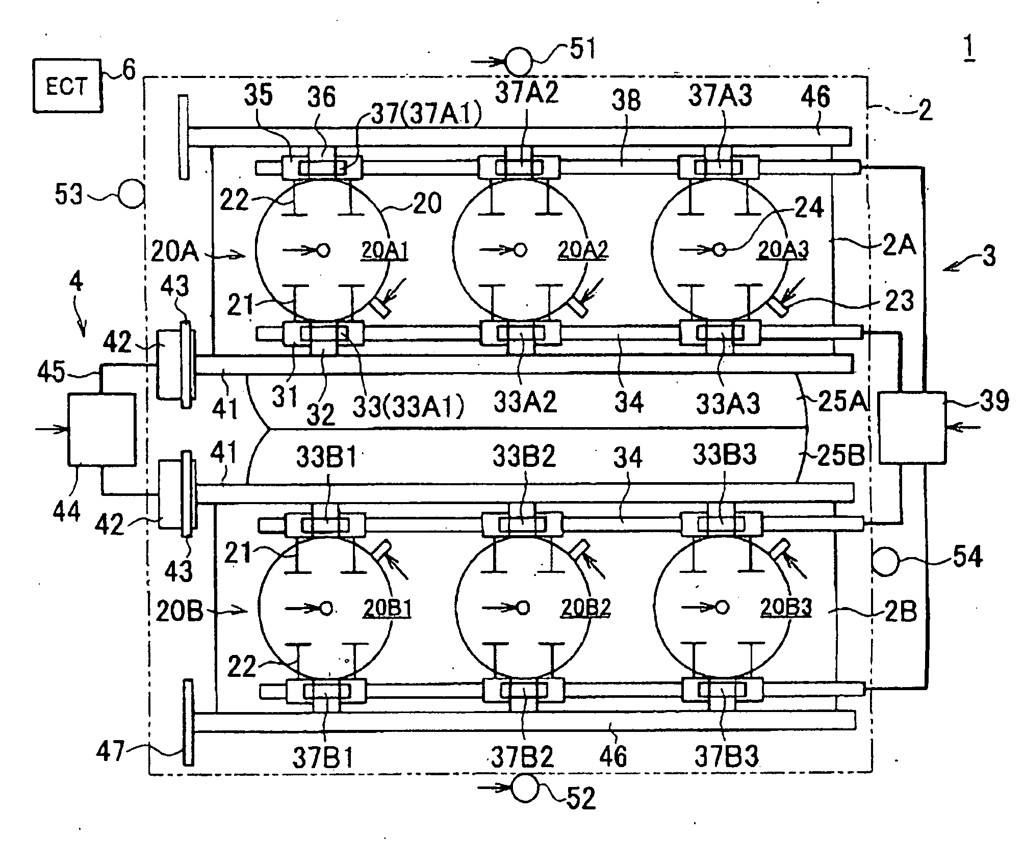
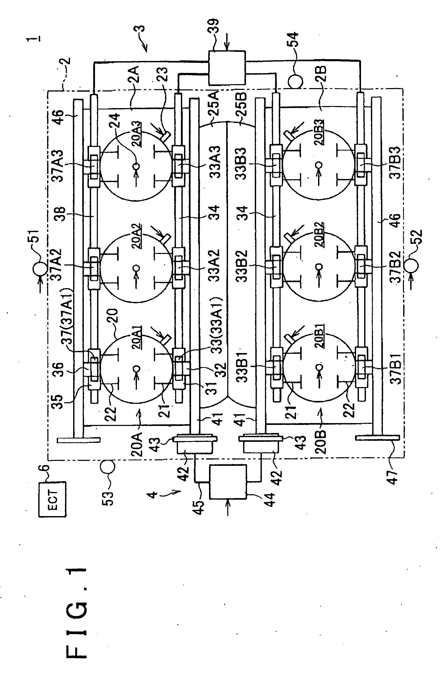
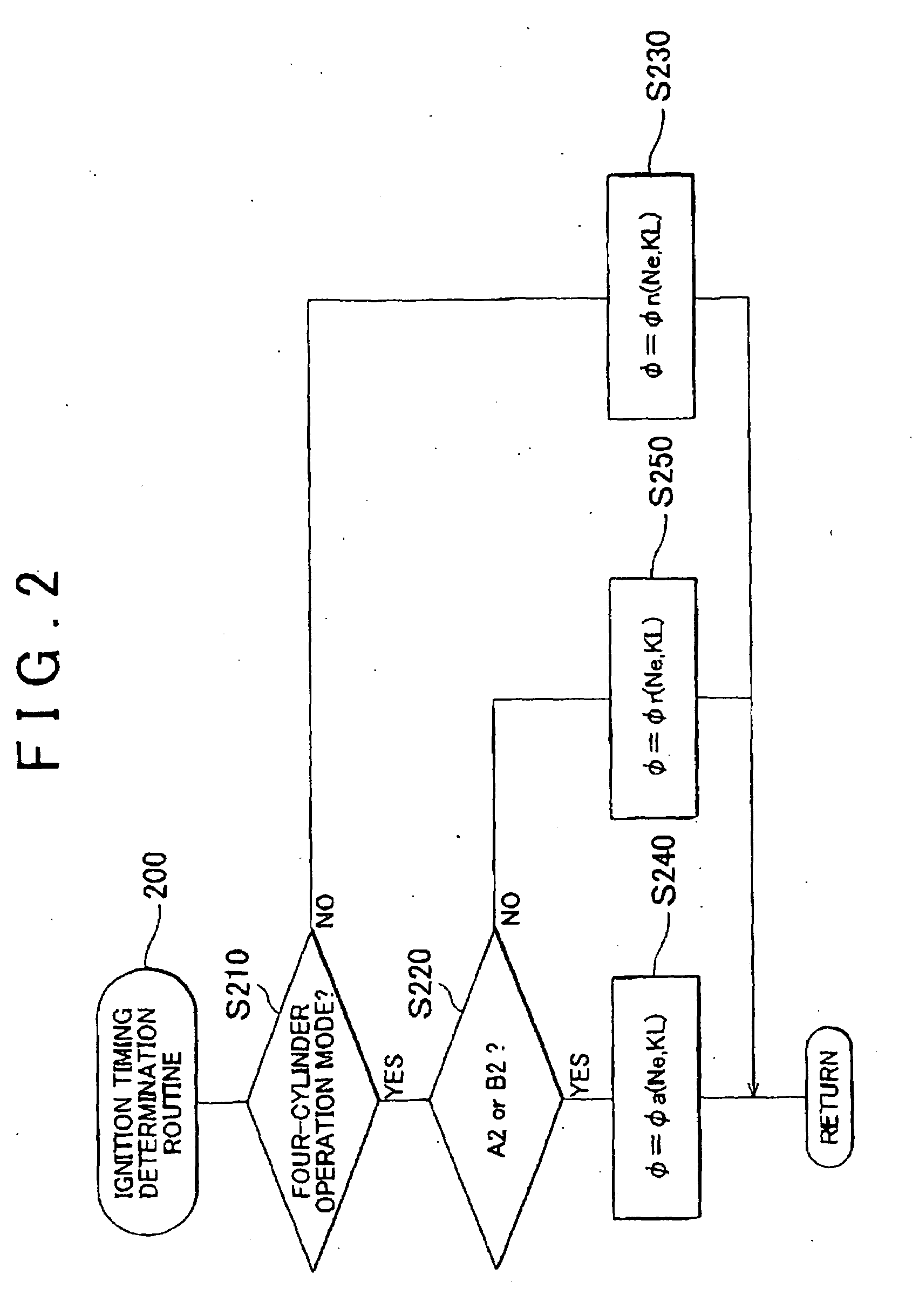
[0048]Hereafter, the invention will be described with reference to FIG. 2. FIG. 2 is a flowchart showing an example of an ignition timing determination routine 200 executed by the ECU 6 shown in FIG. 1. The ECU 6 periodically executes the routine 200 each time the crank angle reaches a predetermined value (e.g. BTDC 90° CA).

[0049]In the routine, it is first determined in S210 whether the current engine operation mode is the four-cylinder operation mode. If it is determined that the current engine operation mode is the four-cylinder operation mode (“YES” in S210), S220 is executed. In S220, it is determined whether the current ignition takes place in one of the cylinder A2 and the cylinder B2. Based on the results of determinations in S210 and S220, ignition timing φ is determined as described below (S230, S240 or S250), after which the routine ends.

[0050]If it is determined that the current engine operation mode is one of the modes in which combustion takes place in the operating cy...

second embodiment

[0053]Hereafter, the invention will be described with reference to FIG. 3. FIG. 3 is a flowchart showing a fuel injection amount determination routine 300 that is executed by the ECU 6 shown in FIG. 1. The ECU 6 periodically executes the routine 300 each time the crank angle reaches a predetermined value.

[0054]In the routine, it is first determined in S310 whether the current engine operation mode is the four-cylinder operation mode. If it is determined that the current engine operation mode is the four-cylinder operation mode (“YES” in S310), S320 is executed. In S320, it is determined whether current fuel injection takes place in one of the cylinder A2 and the cylinder B2. Based on the results of determinations in S310 and S320, a based fuel injection amount Fbase is determined as follows (S330, S340 or S350). Then, the fuel injection amount is corrected based on an output from, for example, an air-fuel ratio sensor, whereby a command fuel injection amount Fi is calculated (S360),...


PUM


Abstract

In some cylinder deactivation modes (e.g. virtual V-four operation mode in which two cylinders of a V-six engine are deactivated), ignition / combustion may take place in operating cylinders at uneven intervals. In this case, the output torque varies between the immediately subsequent operating cylinders after the deactivated cylinders in the firing order and the other operating cylinders. A multicylinder engine includes an ignition timing adjustment unit. When the ignition takes place in the operating cylinders at uneven intervals during cylinder deactivation, the ignition timing adjustment unit adjusts ignition timing in each of the operating cylinders to smooth the output torque of the operating cylinders.

Description

INCORPORATION BY REFERENCE[0001]The disclosure of Japanese Patent Application No. 2008-077900 filed on Mar. 25, 2008 including the specification, drawings and abstract is incorporated herein by reference in its entirety.BACKGROUND OF THE INVENTION[0002]1. Field of the Invention[0003]The invention relates to a multicylinder engine in which part of cylinders may be deactivated, and a method for controlling the same.[0004]2. Description of the Related Art[0005]Multicylinder engines of this type are described in, for example, Japanese Patent Application Publication No. 07-217461 (JP-A-07-217461), Japanese Patent Application Publication No. 2004-300994 (JP-A-2004-300994), Japanese Patent Application Publication No. 2007-15653 (JP-A-2007-15653), Japanese Patent Application Publication No. 2007-23793 (JP-A-2007-23793), and Japanese Patent Application Publication No. 2007-162606 (JP-A-2007-162606). In this type of engine, the vibration developmental state differs between normal engine opera...

Claims


Application Information

Patent Timeline
IPC IPC(8): F02D41/30F02D17/02
CPCF02B75/22F02D13/0238F02D13/06Y02T10/18F02D41/0087F02P5/1512Y02T10/46F02D17/02Y02T10/12Y02T10/40
Inventor SHINAGAWA, TOMOHIROHOSOKAWA, YOUHEI
Owner TOYOTA JIDOSHA KK
Learn More