Rotating electric machine

a rotating electric machine and electric motor technology, applied in the direction of rotating parts of the magnetic circuit, magnetic circuit shape/form/construction, windings, etc., can solve the problems of torque ripple, vibration and noise, which may have otherwise been caused, and is suppressive, so as to achieve the effect of suppressing vibration and nois

Active Publication Date: 2020-10-22
DENSO CORP
View PDF0 Cites 1 Cited by
  • Summary
  • Abstract
  • Description
  • Claims
  • Application Information

AI Technical Summary

Benefits of technology

[0006]It is an object of the present disclosure to provide a rotating electric machine which can suppress vibration and noise.

Problems solved by technology

In such a rotating electric machine, when a phase difference of electric currents is generated between the first inverter and the second inverter, an electromagnetic field generated in a gap between a rotor and a stator by the armature winding may become spatially unbalanced, and may cause torque ripple.
Therefore, vibration and noise, which may have otherwise been caused, are suppressive.

Method used


Image

  • Rotating electric machine
  • Rotating electric machine
  • Rotating electric machine

Examples


first embodiment

[0028]Hereafter, each of the embodiments is described with reference to the drawings. In the following embodiments, same or equivalent parts are denoted by the same reference numbers in the drawings, and the description of the same reference numbers is borrowed from the first one. In the first embodiment, a motor 10 as a rotating electrical machine is described as an example.

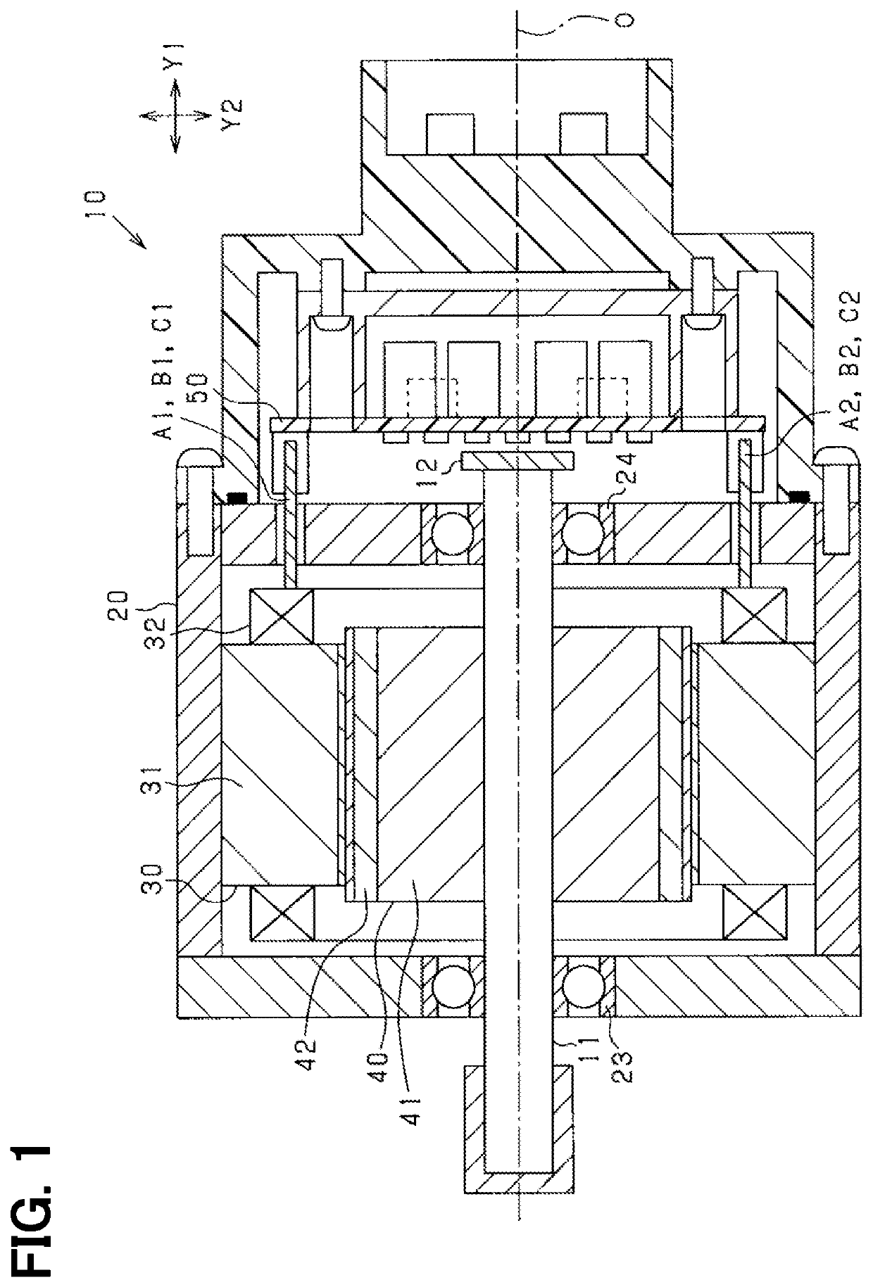
[0029]The motor 10 shown in FIG. 1 is of a permanent magnet field type, and is, more specifically, a permanent magnet field type synchronous machine having a three-phase winding. That is, the motor 10 is a brushless motor. This three-phase winding may have two systems, i.e., two sets of winding wires. The motor 10 includes a housing 20, a stator 30 fixed to the housing 20, a rotor 40 that rotates with respect to the stator 30, and a rotating shaft 11 to which the rotor 40 is fixed. Hereafter, in the present embodiment, an axial direction indicates a direction of axis of the rotating shaft 11 (i.e., direction of ...

second embodiment

[0080]In the first embodiment, the total phase difference is 80 degrees. In the second embodiment, the total phase difference is set to 40 degrees. That is, in the second embodiment, for having 40 degrees as each phase difference of the magnetomotive force of each of the coil bodies Uc, Vc, Wc with respect to the magnetomotive force of each of the coil bodies Ua, Va, Wa, the total phase difference of the magnetomotive force generated by the winding section of the second stator winding 32b wound on each of the third teeth with respect to the magnetomotive force generated by the winding section of the first stator winding 32a wound on each of the third teeth is set to 40 degrees. Note that, though the angle may preferably be set to 40 degrees, the angle may be set to a value within a range of 32 to 48 degrees.

[0081]In such case, the arrangement of the winding sections in each phase is configured as shown in FIGS. 10 and 11. Here, the coil body Uc provided on the tooth T9 is exemplifie...

third embodiment

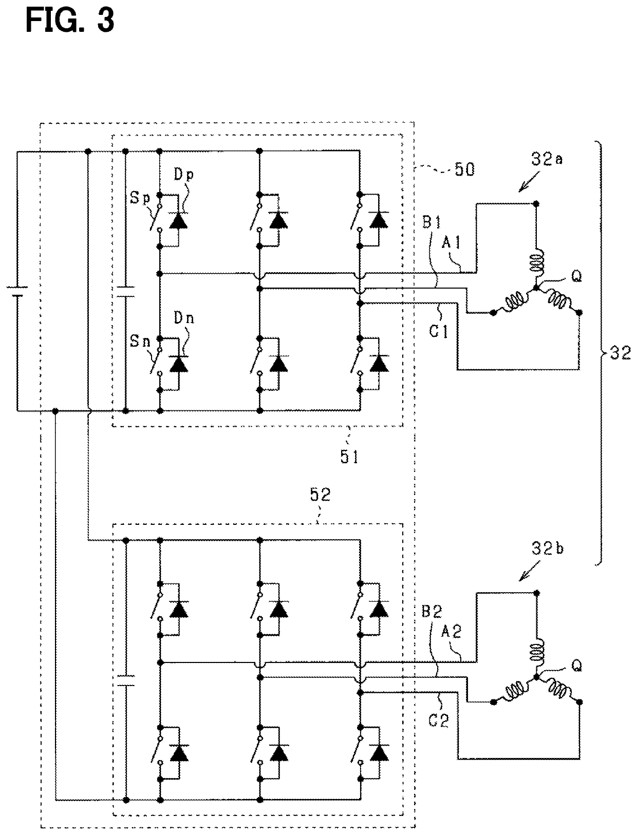
[0090]In the first embodiment, the current phase difference “β” between the first inverter circuit 51 and the second inverter circuit 52 is 20 degrees in electric angle. In the third embodiment, it is set to 40 degrees. That is, each phase difference of the magnetomotive force of each of the coil bodies Ub, Vb, Wb with respect to the magnetomotive force of each of the coil bodies Ua, Va, Wa is 40 degrees.

[0091]Therefore, in the third embodiment, in the equations (13) and (14), the first term corresponds to a component based on the coil bodies Ua, Va, Wa, and the second term corresponds to a component based on the coil bodies Uc, Vc, Wc, and the third term corresponds to a component based on the coil bodies Ub, Vb, Wb.

[0092]Further, in the third embodiment, “λ1” indicates the phase difference of the magnetomotive force of the coil body Uc with respect to the magnetomotive force of the coil body Ua in the U phase, and also indicates the phase difference of the magnetomotive force of t...


PUM


Abstract

A rotating electric machine includes coil bodies formed as a first stator winding wound on first teeth, other coil bodies formed as a second stator winding wound on second teeth, and yet other coil bodies formed as the first stator winding and the second stator winding wound on third teeth. A phase difference between an electric current in the first stator winding wound on the third teeth and an electric current in the second stator winding wound on the third teeth is set so that respective phase differences of magnetomotive forces of the other coil bodies in three phases with respect to respective magnetomotive forces of the coil bodies in three phases and respective phase differences of magnetomotive forces of the yet other coil bodies in three phases with respect to respective magnetomotive forces of the other coil bodies in three phases are 20 degrees in electric angle.

Description

CROSS REFERENCE TO RELATED APPLICATION[0001]The present application is based on and claims the benefit of priority of Japanese Patent Application No. 2019-081377, filed on Apr. 22, 2019, the disclosure of which is incorporated herein by reference.TECHNICAL FIELD[0002]The present disclosure generally relates to a rotating electric machine.BACKGROUND INFORMATION[0003]Conventionally, a rotating electric machine having a first armature winding to which a three-phase current is supplied from a first inverter and a second armature winding to which a three-phase current is supplied from a second inverter is known. In such a rotating electric machine, when a phase difference of electric currents is generated between the first inverter and the second inverter, an electromagnetic field generated in a gap between a rotor and a stator by the armature winding may become spatially unbalanced, and may cause torque ripple.[0004]Therefore, the rotating electric machine disclosed in a related art inc...

Claims


Application Information

Patent Timeline
Patent Type & Authority Applications(United States)
IPC IPC(8): H02K29/03H02K1/14H02K1/27H02K3/28H02K3/52H02K11/33H02K21/16H02K24/00
CPCH02K2213/03H02K1/146H02K29/03H02K21/16H02K2203/06H02K1/276H02K3/28H02K11/33H02K3/522H02K24/00H02K11/21H02K11/04
Inventor KATOU, HIDENORI
Owner DENSO CORP
Why Eureka
Try Eureka