
Testing module, testing apparatus and testing method

a testing module and testing apparatus technology, applied in the direction of detecting faulty computer hardware, instruments, error detection/correction, etc., can solve the problems of lowering the overall testing efficiency of the testing apparatus, and each pattern generator may not be able to generate a test pattern independently

Inactive Publication Date: 2009-10-01
ADVANTEST CORP
View PDF23 Cites 4 Cited by
  • Summary
  • Abstract
  • Description
  • Claims
  • Application Information

AI Technical Summary

Benefits of technology

[0006]Therefore, it is an object of an aspect of the innovations herein to provide a testing apparatus and a testing method which are capable of overcoming the above drawbacks accompanying the related art. The above and other objects can be achieved by combinations described in the independent claims. The dependent claims define further advantageous and exemplary combinations of the innovations herein.

Problems solved by technology

This means that the pattern generators controlled by the single controller receive a single piece of designation information and that each pattern generator may not be capable of generating a test pattern independently.
In other words, one or more redundant pattern generators may not be connected to the test target terminals to be tested and thus not used, which may in turn lower the overall testing efficiency of the testing apparatus.

Method used


Image

  • Testing module, testing apparatus and testing method
  • Testing module, testing apparatus and testing method
  • Testing module, testing apparatus and testing method

Examples


Embodiment Construction

[0018]Some aspects of the invention will now be described based on an embodiment, which does not intend to limit the scope of the present invention, but exemplifies the invention. All of the features and the combinations thereof described in the embodiment are not necessarily essential to the invention.

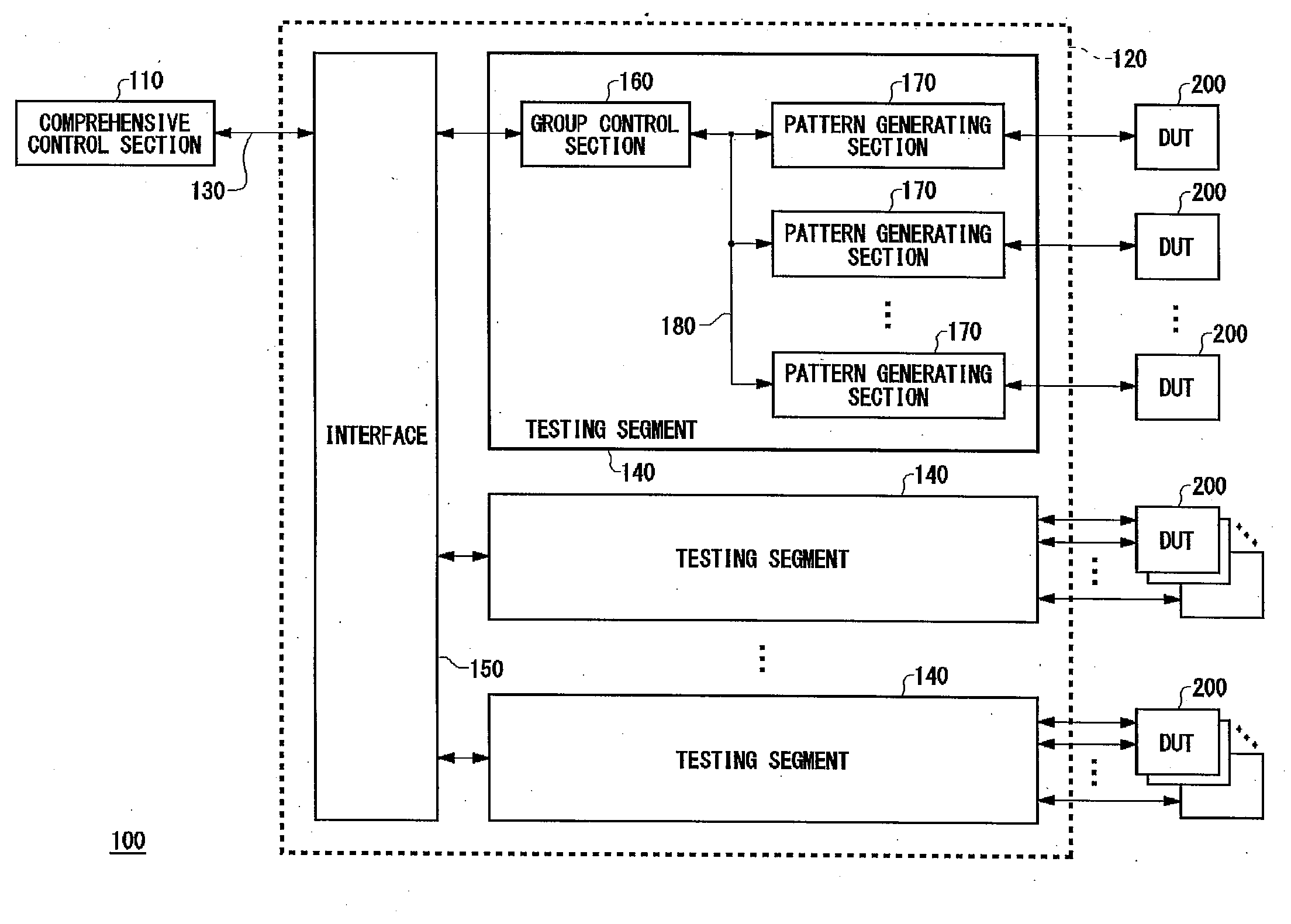
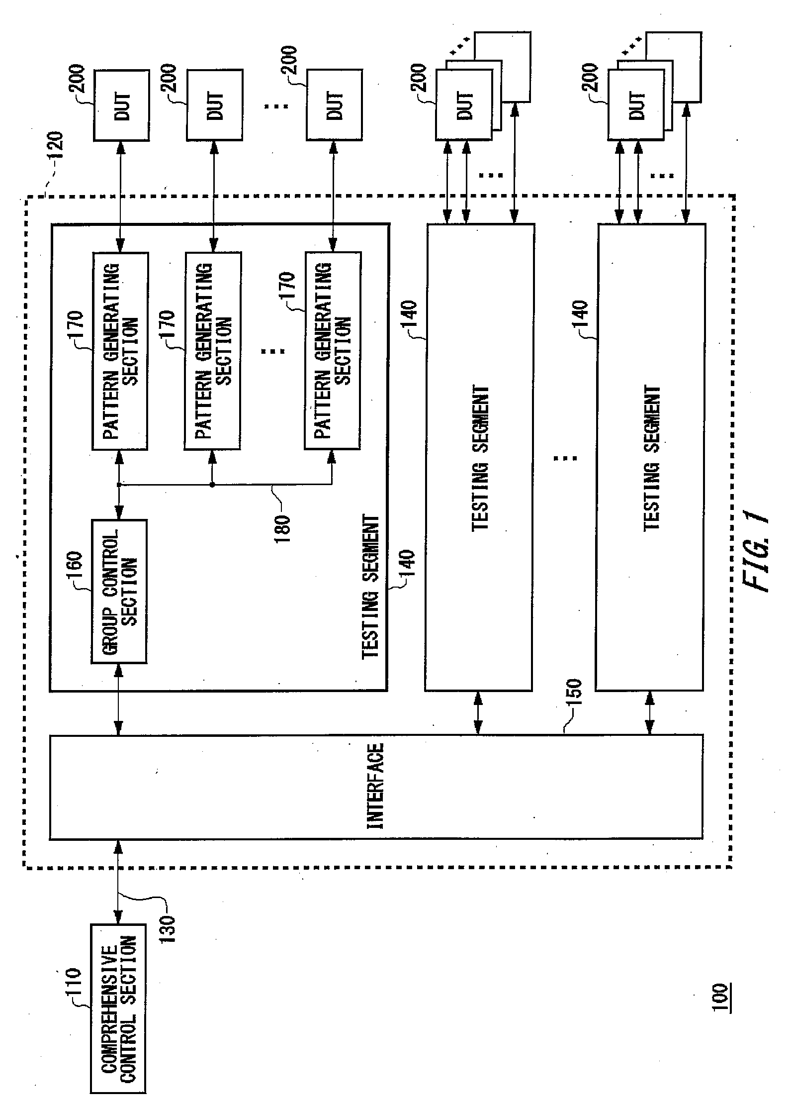
[0019]FIG. 1 is an exemplary functional block diagram illustrating a testing apparatus 100 relating to an embodiment of the present invention, together with devices under test (DUTs) 200. The testing apparatus 100 includes a comprehensive control section 110, a testing module 120, and a standard bus 130. The testing module 120 includes a plurality of testing segments 140 and an interface 150. Each testing segment 140 includes a group control section 160, pattern generating sections 170, and an internal bus 180.

[0020]The comprehensive control section 110 transmits / receives data via the standard bus 130, to control the testing module 120. The comprehensive control section 110 may be an ...


PUM


Abstract

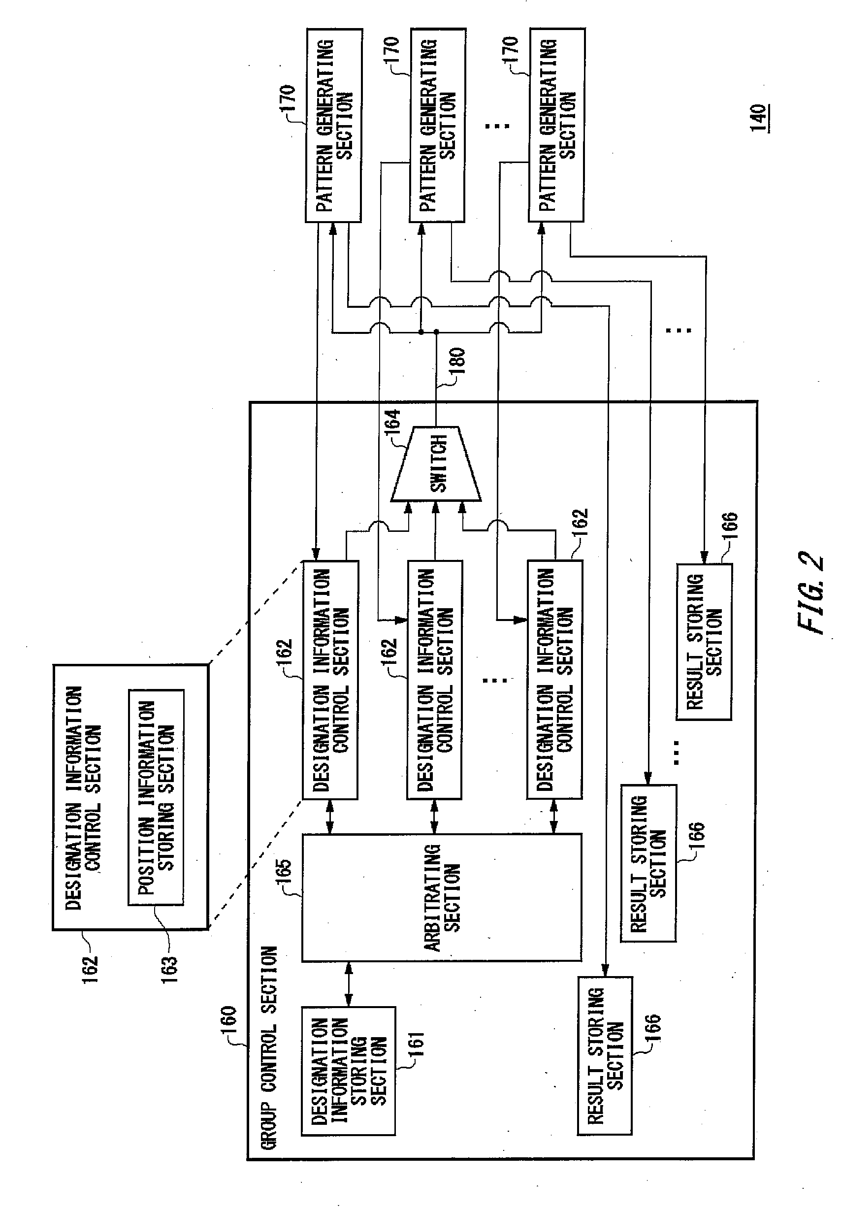
There is provided a testing module including a designation information storing section that stores thereon designation information designating an order of decoding fundamental patterns, a fundamental pattern storing section that stores thereon the fundamental patterns in a data form, a plurality of pattern generating sections each of which has a designation information temporary storing section that temporarily stores thereon part of the designation information, where each pattern generating section generates a test pattern to be supplied to a device under test by decoding the fundamental patterns in an order designated by the partial designation information stored on the designation information temporary storing section, a plurality of position information storing sections each of which stores thereon, in association with a corresponding one of the plurality of pattern generating sections, position information designating a read position from which the designation information is read from the designation information storing section, and an information transmission path that is shared by the plurality of pattern generating sections, where the information transmission path transmits the partial designation information from the designation information storing section to the designation information temporary storing section in each pattern generating section.

Description

BACKGROUND[0001]1. Technical Field[0002]The present invention relates to a testing module, a testing apparatus and a testing method. More particularly, the present invention relates to a testing module, a testing apparatus and a testing method which suitably test a large number of relatively small-size semiconductor devices.[0003]2. Related Art[0004]Japanese Patent Application Publication No. 2005-249735 discloses a pattern generator and a testing apparatus which are capable of efficiently generating a continuous test pattern used for testing an electronic device. The pattern generator disclosed in the above publication first stores test data blocks onto a cache memory in an order designated by designation information, and then sequentially outputs the test data blocks stored on the cache memory as a test pattern. According to the above publication, a single controller controls a plurality of pattern generators, and the pattern generators under the control of the controller test a s...

Claims


Application Information

Patent Timeline
Patent Type & Authority Applications(United States)
IPC IPC(8): G11C29/08G06F11/26
CPCG01R31/31919
Inventor AKHTAR, SAMIMURATA, KIYOSHISUGAYA, TOMOYUKI
Owner ADVANTEST CORP
Learn More