Decoy structure

Inactive Publication Date: 2009-10-08
ARNOLD JOSEPH S
View PDF30 Cites 25 Cited by
  • Summary
  • Abstract
  • Description
  • Claims
  • Application Information

AI Technical Summary

Benefits of technology

[0010]The decoy may be compressed by squeezing the ribs to curl toward one another, thus reducing the diameter of the structure and allowing it to be inserted in a storage tube. The support rod and its weighted base are swung rearwardly through the open bottom side of the frame due to the spring attachment of the upper end of the support rod to the spine. When the decoy is to be deployed, the hunter need only withdraw it from its storage tube and toss it into the desired area. The resilient frame will promptly spring to

Problems solved by technology

Obviously, such decoys cannot be tossed into position at all.
In addition to the above consideration, most such heavier decoys have sufficient upper mass that they will generally tip over if tossed randomly into the field.
Such flotation decoys will generally promptly right themselves when tossed into the water, but will often remain tipped over on dry land if they

Method used


Image

  • Decoy structure
  • Decoy structure
  • Decoy structure

Examples


Example

[0019]Similar reference characters denote corresponding features consistently throughout the attached drawings.

DETAILED DESCRIPTION OF THE PREFERRED EMBODIMENTS

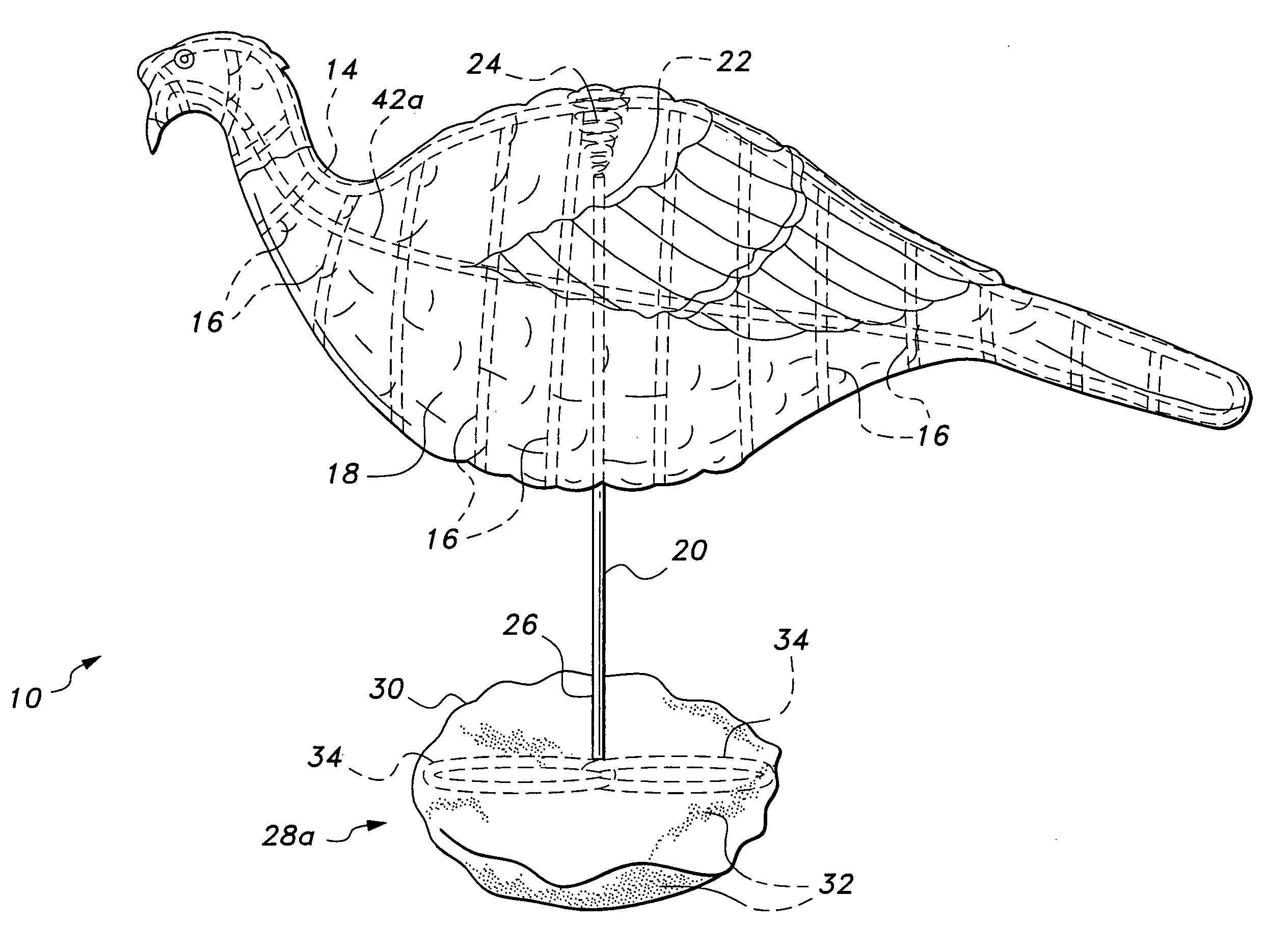
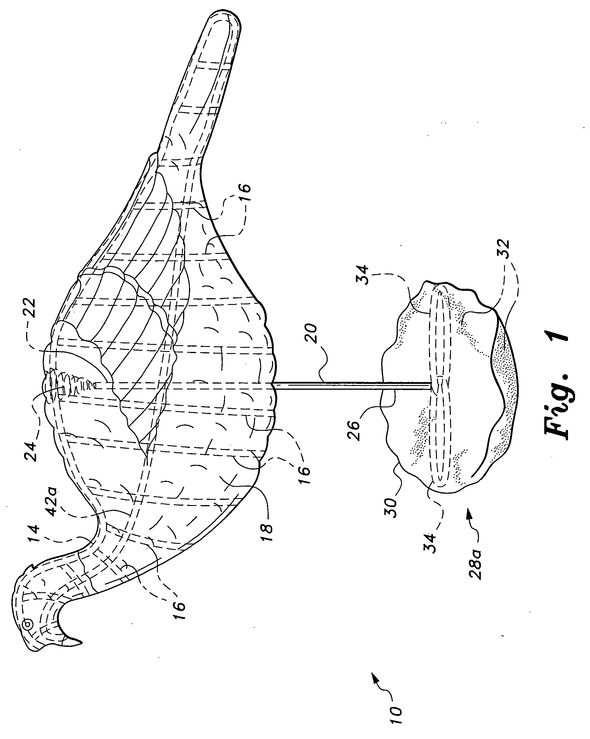
[0020]The present invention relates to various embodiments of a decoy structure that is configured to provide a lightweight and easily portable device that can be quickly deployed in the field with minimal preparation and effort. FIG. 1 of the drawings provides a left side perspective view of an exemplary decoy structure according to the present invention, comprising a turkey decoy 10. It will be understood that innumerable other representations of game animals may be formed using the general structural elements of the present decoy structure. The turkey decoy 10 is but one example of such a structure.

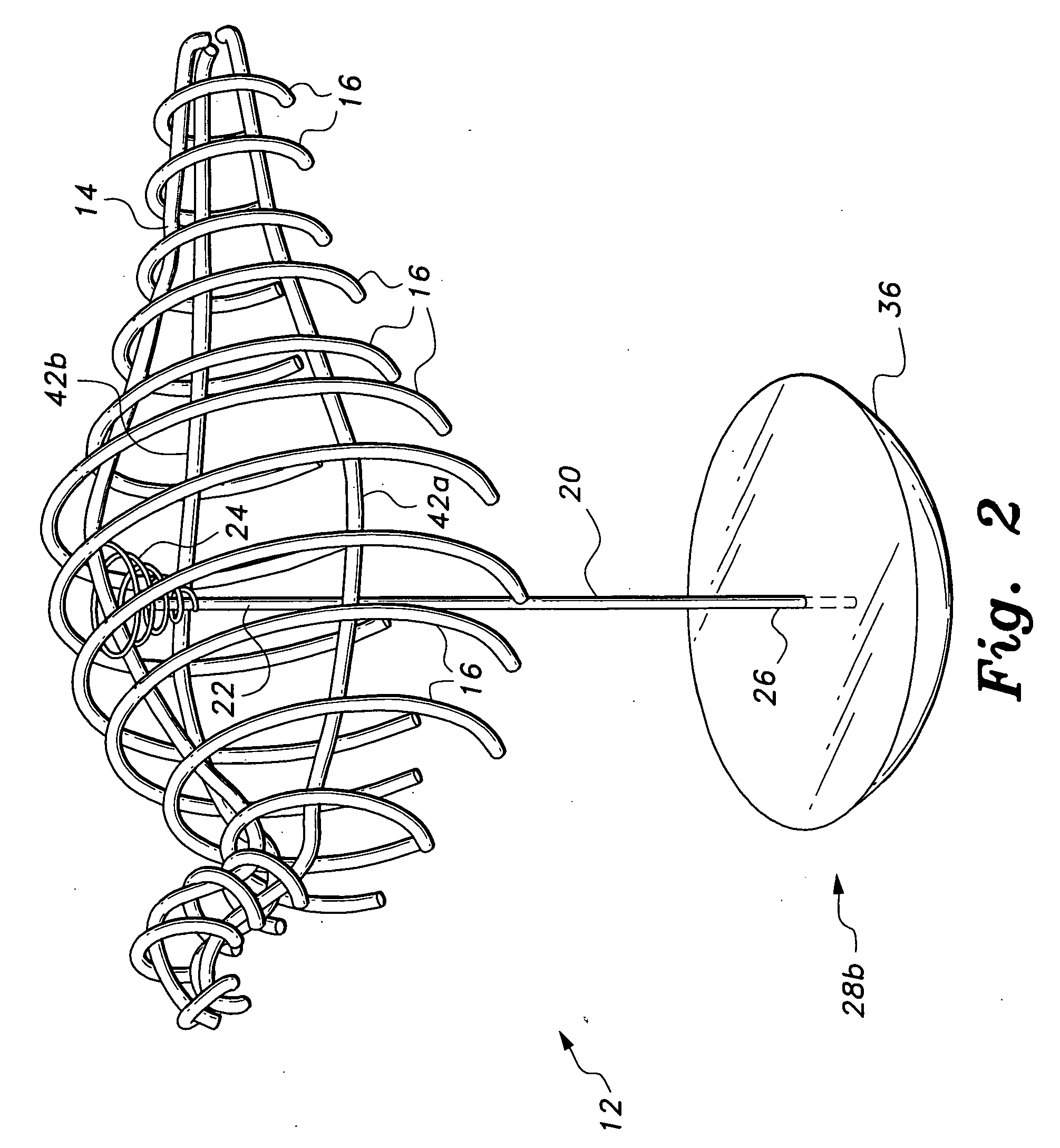
[0021]The turkey decoy 10 has a frame 12 (best shown in FIG. 2) formed of a plurality of thin, flexible, elongate elements comprising an elongate spine 14 having permanently attached (e.g., welded, bonded, etc.) ribs 16 substant...


PUM


Abstract

The decoy structure is formed of a central upper spine and lateral ribs, with a support rod resiliently attached to the approximate midpoint of the spine. The lower end of the support rod has a weighted base. A removable flexible cover is patterned to resemble the object game, and is open at the bottom. This allows the ribs to be curled inwardly toward one another with their distal ends and lower portions of the cover overlapping to reduce the structure diameter for compact storage. The support rod swings rearwardly through the open bottom of the structure, allowing the decoy to be stored in a small diameter tube. The decoy is quickly deployed by withdrawing it from its tube and tossing it to the desired location. The weighted base deploys downwardly, with aerodynamic drag holding the body above the base as it lands to orient the decoy properly in the field.

Description

CROSS-REFERENCE TO RELATED APPLICATION[0001]This application claims the benefit of U.S. Provisional Patent Application Ser. No. 61 / 064978, filed Apr. 7, 2008.BACKGROUND OF THE INVENTION[0002]1. Field of the Invention[0003]The present invention relates generally to hunting paraphernalia, and more particularly to a decoy structure having a spine and a series of lateral ribs formed of wire or other thin, resilient material and having a lightweight cover removably installed thereon. A weighted base is also provided.[0004]2. Description of the Related Art[0005]Decoys have long been used in hunting to attract game. Most such decoys are formed of solid and relatively dense material, or at least have a relatively hard and dense shell. Most such decoys must be placed specifically by the hunter; they are sufficiently massive that they cannot be tossed more than several feet to a location beyond that of the concealed hunter. This is even more true of decoys having special bases, spikes, etc., ...

Claims


Application Information

Patent Timeline
IPC IPC(8): A01M31/06
CPCA01M31/06
Inventor ARNOLD, JOSEPH S.
Owner ARNOLD JOSEPH S
Why Eureka
Try Eureka