Automobile gearshift lever lock assembly

Inactive Publication Date: 2009-10-08
ONE LUS INT
View PDF25 Cites 1 Cited by
  • Summary
  • Abstract
  • Description
  • Claims
  • Application Information

AI Technical Summary

Benefits of technology

[0007]The primary purpose of the present invention is to provide an automobile gearshift lever lock, comprising an outer decorative cover, a latch, a lock, a coupling element, and a steel mounting plate. The lock comprises a core and a securing mechanism. The lock is housed, around an outer circumference thereof, by a lock shell. The coupling element forms an open channel. The lock shell is fit into the open channel of the coupling element and fit over the lock to form a unitary device, which can be mounted to the mounting plate by various means. Opposite sides of the lock are protected by protection members. The core is provided, on a front surface thereof, with a protective face plate. As such, the mechanical strength of the lock is enhanced and the lock can be protected against any damage to thereby reduce the chance of automobile burglary.

Problems solved by technology

The two legs thus restrain the displacement of the gearshift lever, thereby making it impossible to effect gear shifting for protecting the automobile from burglary.
Such a conventional gearshift lever lock is arranged beside the enclosure of the transmission box, namely the lock is exposed, and it thus is not of visual aesthetics.
Also the exposure and protrusion of the lock interferes with the movement of automobile seat and passengers.
Again, interference with the movement of automobile chair and passengers occur.
Thus, although automobiles of some models or brads may have sufficient interior space inside the transmission box enclosure to accommodate the mounting plate 11 and the lock 1, yet others do not have sufficient interior space for the mounting plate 11 and the lock 1, especially for the economic small-sized cars.
However, again, this known lock as a whole is still bulky and may not be fit for automobiles of all models and brands.
It also surfers the problem of lock projecting beyond the side wall of the transmission box enclosure.

Method used


Image

  • Automobile gearshift lever lock assembly
  • Automobile gearshift lever lock assembly
  • Automobile gearshift lever lock assembly

Examples


Embodiment Construction

[0020]The following descriptions are of exemplary embodiments only, and are not intended to limit the scope, applicability or configuration of the invention in any way. Rather, the following description provides a convenient illustration for implementing exemplary embodiments of the invention. Various changes to the described embodiments may be made in the function and arrangement of the elements described without departing from the scope of the invention as set forth in the appended claims.

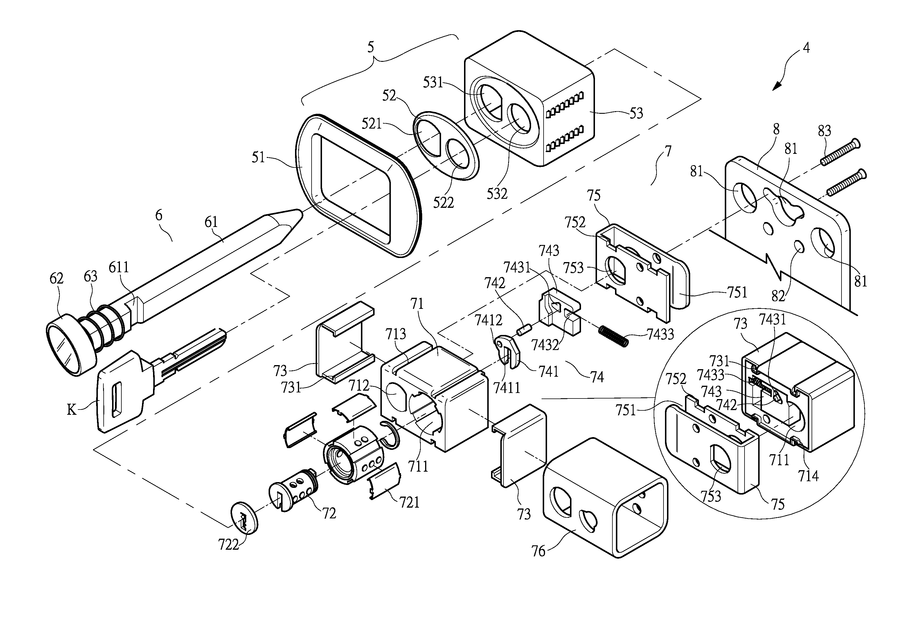
[0021]With reference to the drawings and in particular to FIG. 4, an automobile gearshift lever lock assembly constructed in accordance with the present invention, generally designated at 4, comprises an outer decorative cover 5, a latch 6, a lock 7, and a mounting plate 8, which is preferably made of steel.

[0022]The outer cover 5 comprises a decorative frame 51, a face plate 52, and a case 53. The frame 51 is mounted to an outside surface of an enclosure of an automobile transmission box (not sh...


PUM


Abstract

An automobile gearshift lever lock includes an outer decorative cover, a latch, a lock, a coupling element, and a steel mounting plate. The lock includes a core and a securing mechanism. The lock is housed, around an outer circumference thereof, by a lock shell. The coupling element forms an open channel. The lock shell is fit into the open channel of the coupling element and fit over the lock to form a unitary device, which can be mounted to the mounting plate by various means. Opposite sides of the lock are protected by protection members. The core is provided, on a front surface thereof, with a protective face plate. As such, the mechanical strength of the lock is enhanced and the lock can be protected against any damage to thereby reduce the chance of automobile burglary.

Description

BACKGROUND OF THE INVENTION[0001](a) Technical Field of the Invention[0002]The present invention relates to an automobile gearshift lever lock, and in particular to an automobile gearshift lever lock that comprises protective members to protect the lock from being damaged.[0003](b) Description of the Prior Art[0004]A conventional gearshift lever lock comprises a mounting plate arranged by an enclosure of an automobile transmission box and a lock is bolted to the mounting plate. The lock forms two symmetric locking holes into which two legs of a U-shaped latch extend to be positioned at front and rear sides of the gearshift lever. The two legs thus restrain the displacement of the gearshift lever, thereby making it impossible to effect gear shifting for protecting the automobile from burglary. Such a conventional gearshift lever lock is arranged beside the enclosure of the transmission box, namely the lock is exposed, and it thus is not of visual aesthetics. Also the exposure and pro...

Claims


Application Information

Patent Timeline
IPC IPC(8): E05B65/12
CPCE05C1/12B60R25/066Y10T70/5934
Inventor WU, PING-HUA
Owner ONE LUS INT
Why Eureka
Try Eureka