Shielding cage assembly with reinforcing dividing walls

Active Publication Date: 2006-05-02
GOOGLE LLC
View PDF5 Cites 6 Cited by
  • Summary
  • Abstract
  • Description
  • Claims
  • Application Information

AI Technical Summary

Benefits of technology

[0009]The mechanical strength of the shielding cage assembly at front openings of the cavities is enhanced by the barbs of the dividing walls being engaged in the cutouts of the body cage and the cover cage. The shielding cage assembly can therefore withstand repeated insertion and removal of the transceiver modules without sustaining expansion or distortion. In addition, the shielding cage assembly can reduce costs and achieve a high-density assembly by closely accommodating the plurality of transceiver modules therein. Furthermore, EMI shielding of the transceiver modules is achieved by the shielding cage assembly being made of electrically conductive material.

Problems solved by technology

Furthermore, when the group of transceiver modules is attached to a printed circuit board, it is difficult to achieve a high-density assembly because of the combined bulk of the cages.
However, the strength of the shielding cage assembly at front ends of the dividing walls is limited.
After repeated plugging and unplugging of transceiver modules, the shielding cage assembly is liable to become fatigued, and openings of the spaces at the front of the shielding cage assembly may expand.
When this happens, the transceiver modules may no longer be able to be securely connected in the shielding cage assembly, and the operation of the transceiver modules may be impaired or disrupted.

Method used


Image

  • Shielding cage assembly with reinforcing dividing walls
  • Shielding cage assembly with reinforcing dividing walls
  • Shielding cage assembly with reinforcing dividing walls

Examples


Embodiment Construction

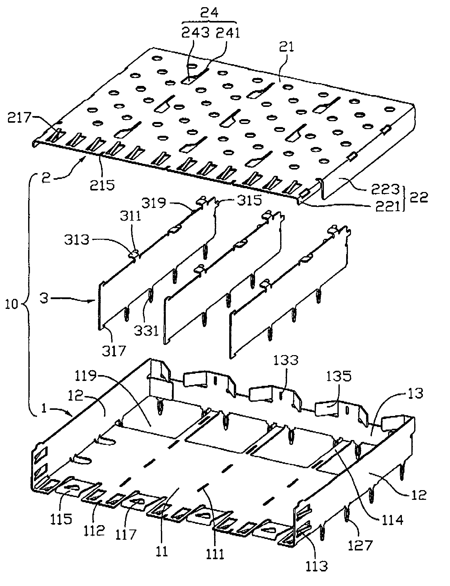
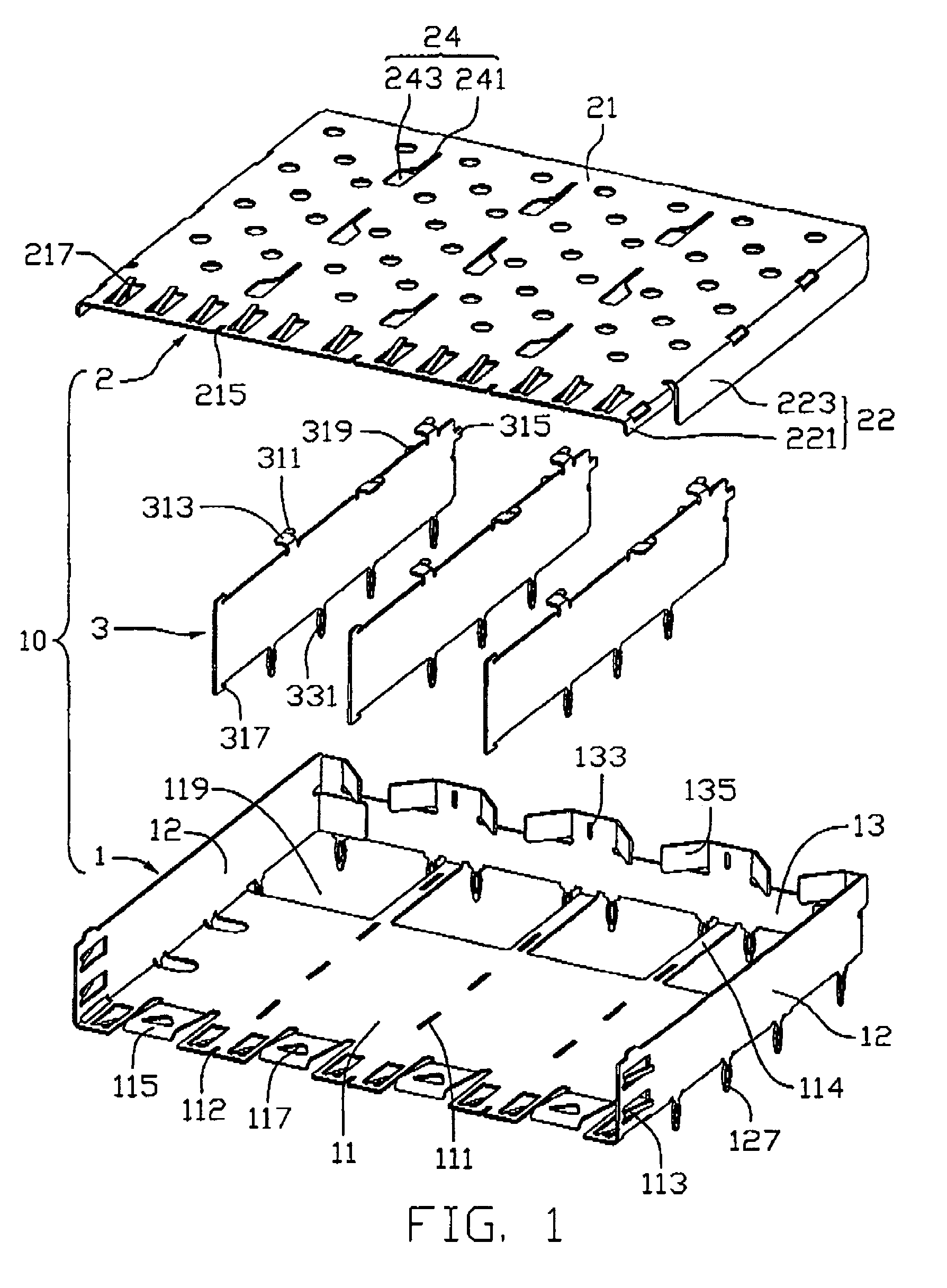
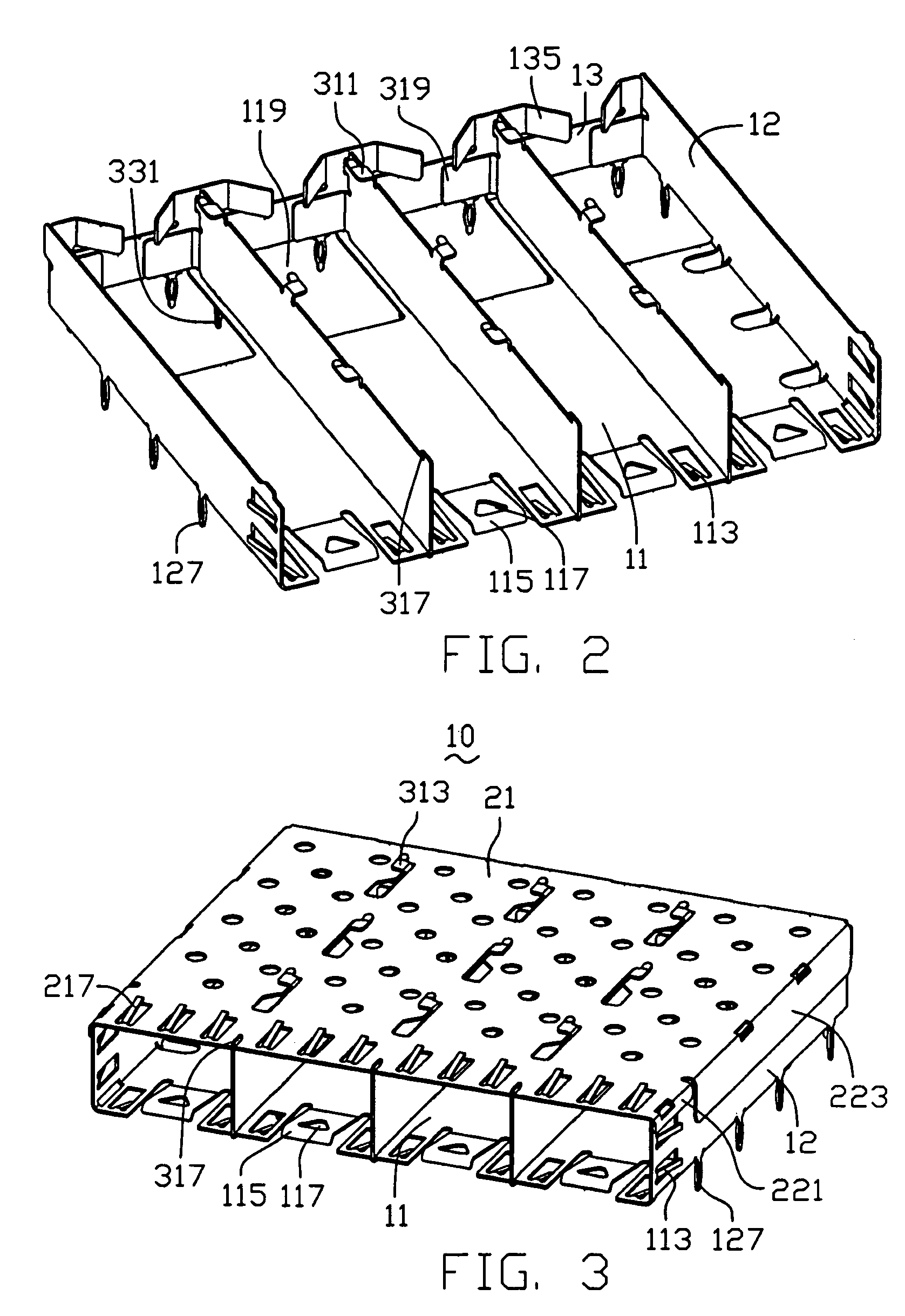
[0014]Referring to FIG. 1, a shielding cage assembly 10 in accordance with the present invention is made of electrically conductive material, and comprises a body cage 1, a cover cage 2 and a plurality of dividing walls 3. The body cage 1, the cover cage 2 and the dividing walls 3 cooperatively form a plurality of cavities for receiving a plurality of transceiver modules (not shown) therein.

[0015]The body cage 1 includes a bottom wall 11, two side walls 12, and a back wall 13. The side walls 12 extend up from two sides of the bottom wall 11 respectively. The bottom wall 11 defines a plurality of bottom openings 119 aligned adjacent the back wall 13, thereby a plurality of end portions 114 is formed in the bottom wall 11. The back wall 13 extends up from the end portions 114 of the bottom wall 11. Electrical connectors can extend into the shielding cage assembly 10 and connect with corresponding transceiver modules through the bottom openings 119 of the bottom wall 11. A plurality of...


PUM


Abstract

A shielding cage assembly (10) for accommodating transceiver modules includes a body cage (1), a cover cage (2), and dividing walls (3). The body cage includes a bottom wall (11) with front cutouts (112), and two side walls (12). The cover cage includes a top wall (21) with front cutouts (215). Each dividing wall has top and bottom barbs (317) at a front end thereof. In assembly, the barbs are engaged in the corresponding cutouts. The bottom wall, side walls, dividing walls and cover cage cooperatively define cavities therebetween for receiving the transceiver modules. The mechanical strength of the shielding cage assembly at front openings of the cavities is enhanced by the barbs of the dividing walls being engaged in the cutouts of the body cage and the cover cage. The shielding cage assembly can therefore withstand repeated insertion and removal of the transceiver modules without sustaining expansion or distortion.

Description

BACKGROUND OF THE INVENTION[0001]1. Field of the Invention[0002]The present invention relates to shielding cages for shielding electronic apparatuses accommodated therein from electromagnetic interference (EMI), and particularly to a shielding cage assembly for receiving a plurality of transceiver modules therein.[0003]2. Prior Art[0004]A transceiver module is a discrete unit used in interface communication equipment. U.S. Pat. No. 6,517,382 discloses a receptacle for a pluggable module. The module is singly received in the receptacle, which provides shielding against EMI. Conventionally, a group of transceiver modules is received in respective individual cages. The need for a plurality of cages multiplies costs proportionately. Furthermore, when the group of transceiver modules is attached to a printed circuit board, it is difficult to achieve a high-density assembly because of the combined bulk of the cages.[0005]U.S. Pat. No. 6,724,641 entitled “Shielding Cage Assembly Adapted Fo...

Claims


Application Information

Patent Timeline
IPC IPC(8): H01R13/648H01R13/658H05K9/00
CPCH01R13/65807H01R13/6594H01R13/6587H05K9/0058
Inventor LEE, CHIEH
Owner GOOGLE LLC
Why Eureka
Try Eureka