Anaesthesia apparatus and method for operating an anaesthesia apparatus

an anaesthesia apparatus and anaesthesia technology, applied in the field of anaesthesia apparatus and a method for operating an anaesthesia apparatus, can solve the problems of high cost and cumbersomeness

Active Publication Date: 2009-10-08
MAQUET CRITICAL CARE
View PDF10 Cites 65 Cited by
  • Summary
  • Abstract
  • Description
  • Claims
  • Application Information

AI Technical Summary

Benefits of technology

[0020]The first embodiment is also feasible for pre-use check. The evacuation valve can be used during pre-use check to eliminate the need for operator action during pre-use check.

Problems solved by technology

Alternatively the whole filter must be replaced by a new filter, which is expensive and cumber-some.

Method used


Image

  • Anaesthesia apparatus and method for operating an anaesthesia apparatus
  • Anaesthesia apparatus and method for operating an anaesthesia apparatus
  • Anaesthesia apparatus and method for operating an anaesthesia apparatus

Examples


Embodiment Construction

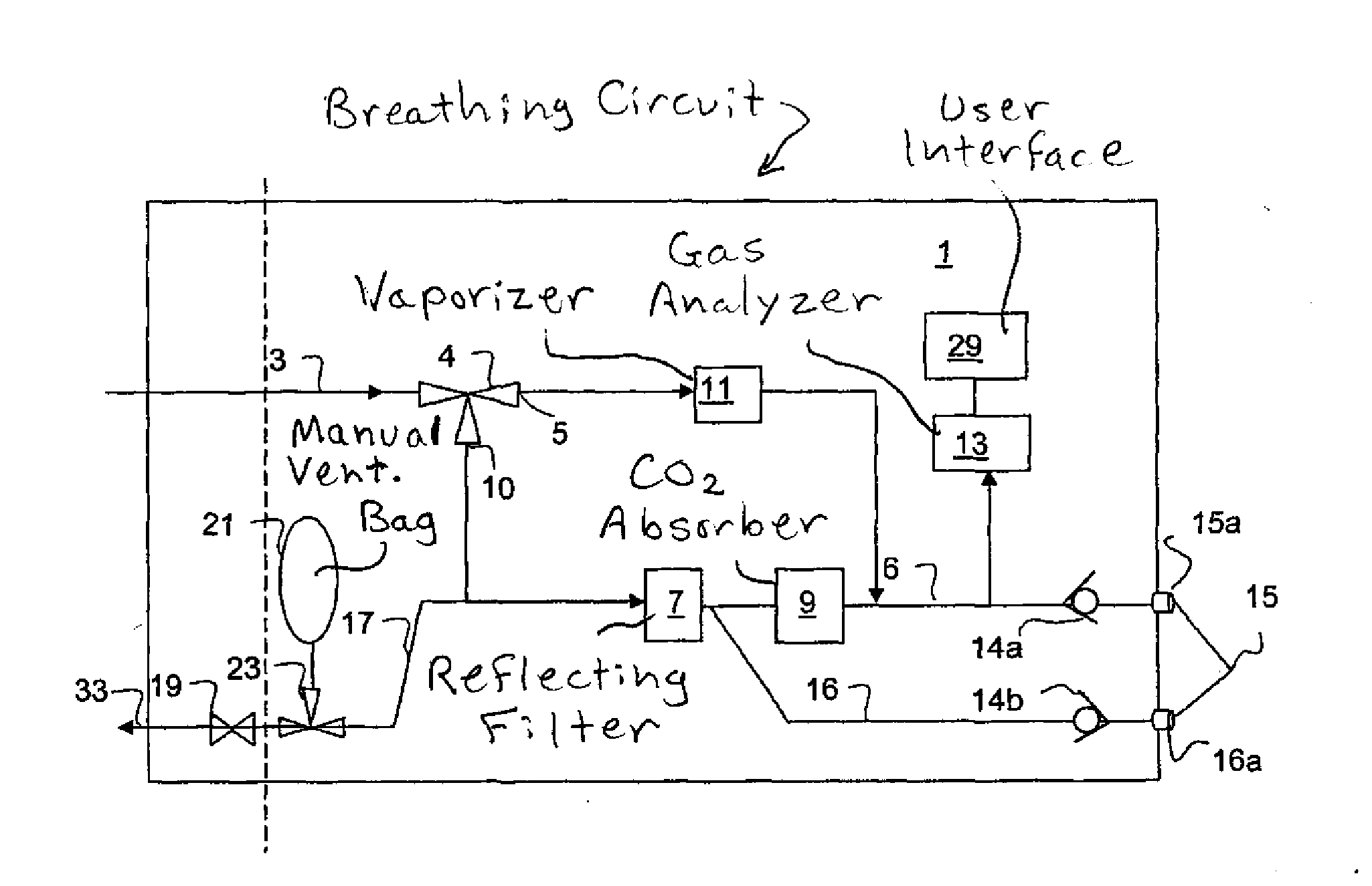
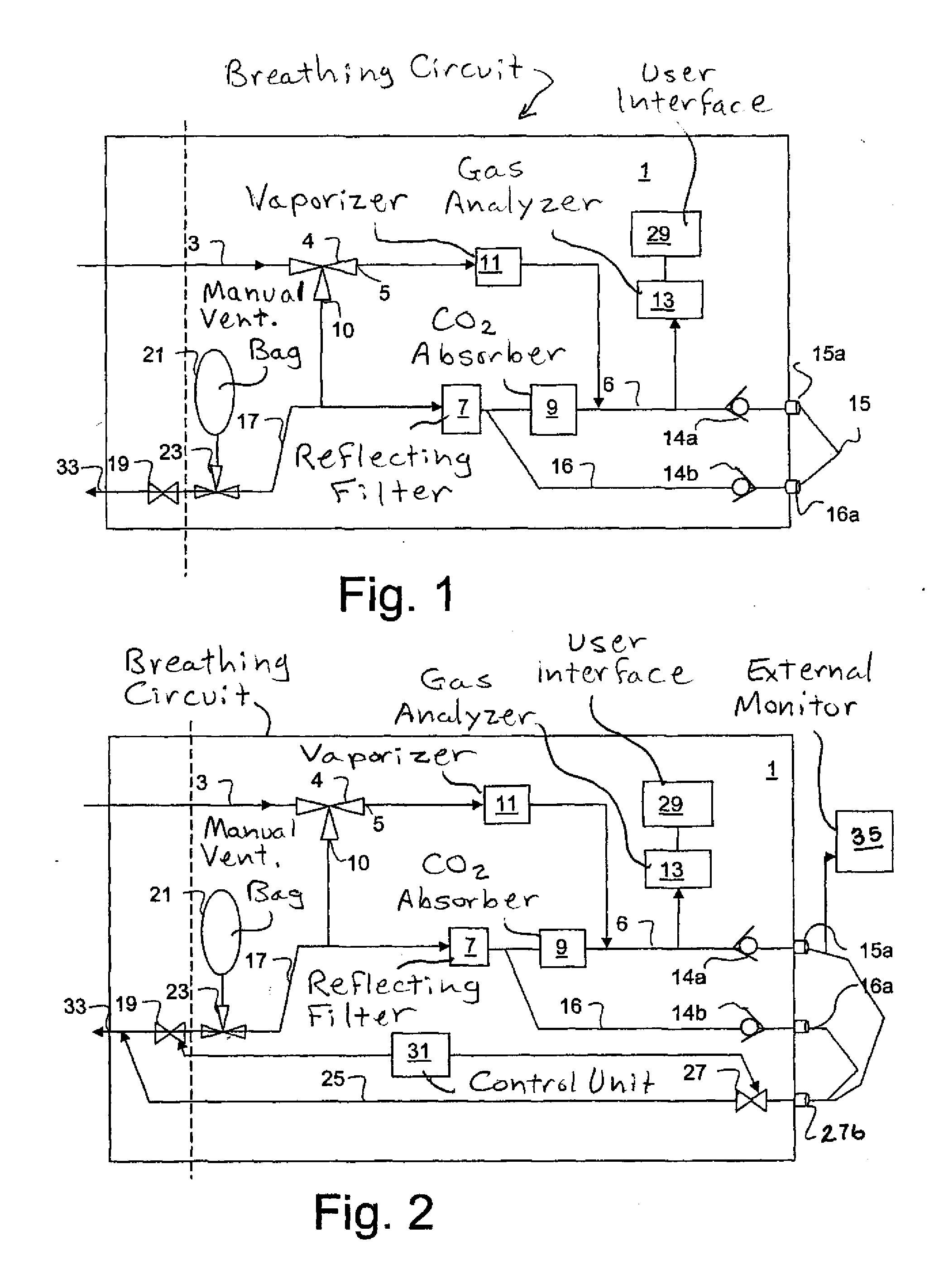
[0031]FIG. 1 shows an anaesthetic apparatus. The breathing circuit 1 includes an input 3 from a ventilator (not shown) to an adjustable selection valve, or shunt valve 4. Through a first outlet 10 of the shunt valve 4 the main part of the breathing gas is provided to a common line 17 that includes a reflecting filter 7. The common line is branched to an inspiration line 6 carrying breathing air to the patient and an expiration line 16 carrying expired air from the patient. The reflecting filter is arranged to adsorb anaesthetic agents exhaled by the patient so that it will not be evacuated with the bulk of the breathing gas. Instead, during the next inhalation the anaesthetic in the reflecting filter 7 will be desorbed and returned to the patient. A CO2 absorber 9 is connected in series with the reflecting filter 7 in the inspiration line 6 between the reflecting filter 7 and the patient.

[0032]Through a second outlet 5 of the shunt valve 4 a smaller part of the breathing gas is prov...


PUM


Abstract

An anaesthesia apparatus has a control unit that controls a gas flow of a flushing gas through at least part of the anaesthesia apparatus so as to flush anaesthetic agent from the apparatus when the apparatus is not connected to a patient. In this way the remaining anaesthetic agent can be removed from the anaesthesia apparatus after use before connecting another patient. Pre-use check of the apparatus can be performed automatically.

Description

BACKGROUND OF THE INVENTION[0001]1. Field of the Invention[0002]The present invention relates to an anaesthesia apparatus and to a method for operating an anaesthesia apparatus. In particular the invention relates to an anaesthesia apparatus comprising a reflector filter for reflecting anaesthetic agent exhaled from the patient.[0003]2. Description of the Prior Art[0004]Anaesthesia apparatuses are known in the art for providing anaesthetics to patients. The term “anaesthesia apparatus” as used herein encompasses also sedation apparatuses, which are a simpler form of anaesthesia apparatus.[0005]Anaesthesia apparatuses typically have inspiration and expiration lines for providing and withdrawing breathing gas from the patient and a vaporizer for providing anesthetic into the breathing gas flow. The vaporizer can be placed in the inspiration line or in a branch connected with the inspiration line, to provide vaporized anaesthetic to the breathing gas flow. The inspiration and expiratio...

Claims


Application Information

Patent Timeline
Patent Type & Authority Applications(United States)
IPC IPC(8): A61M16/01
CPCA61M16/009A61M16/01A61M16/104A61M16/1015A61M2016/1035Y10S128/91A61M16/22A61M16/0093
Inventor LONCAR, MARIOAHLMEN, CHRISTERBROBORG, STEFAN
Owner MAQUET CRITICAL CARE
Why Eureka
Try Eureka