
Hot water corrugated heat transfer tube

a heat transfer tube and corrugated technology, applied in tubular elements, corrosion prevention, coatings, etc., can solve the problems of increasing the pressure loss of the flow inside the tube, unable to achieve efficient heat exchange, etc., to prevent a reduction in the effect of heat transfer and reduce the heat transfer

Inactive Publication Date: 2009-10-08
TSINGHUA UNIV +1
View PDF14 Cites 5 Cited by
  • Summary
  • Abstract
  • Description
  • Claims
  • Application Information

AI Technical Summary

Benefits of technology

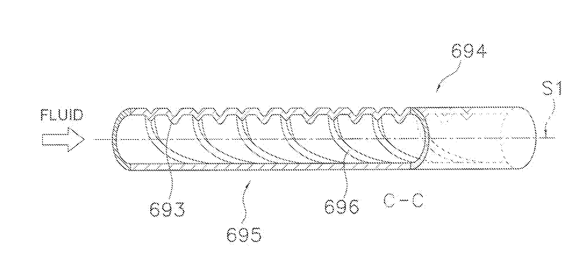
The present invention provides a hot water corrugated heat transfer tube that improves heat transfer performance in the low Reynolds number section where the flow of the fluid inside the tube is in transition from the laminar flow zone to the turbulent flow zone. The invention achieves this by providing projections on the inner surface of the tube in this section, which reduces friction and pressure loss inside the tube, and minimizes the impact on the heat transfer coefficient. The projections have a height of 0.1-0.15 times the inner diameter of the tube, and are spaced apart from each other to avoid increasing the friction factor. The invention provides a simple solution to improve heat transfer performance in this low Reynolds number section, and ensures high efficiency of the hot water corrugated heat transfer tube.

Problems solved by technology

In addition, efficient heat exchange cannot be expected because the thermal conductivity is also small in the low temperature section in the vicinity of the water inlet.
Further, since the corrugated tube causes a strong turbulence at the boundary of the tube wall, the friction factor inside the tube increases considerably compared to a smooth tube depending on the depth of the corrugated groove, which consequently increases the pressure loss of the flow inside the tube.

Method used


Image

  • Hot water corrugated heat transfer tube
  • Hot water corrugated heat transfer tube
  • Hot water corrugated heat transfer tube

Examples


experiment 1

(1) Experiment 1

[0094]FIG. 5(a) is a cross sectional perspective view of the corrugated heat transfer tube 31. In Experiment 1, projections each having the height H1 are provided vertically symmetric on the tube inner surface having an inner diameter D of 8.0 mm in which the corrugated grooves 316 having a depth of Hm are provided. FIG. 5(b) is a cross sectional view taken along the A-A arrow in FIG. 5(a), and FIG. 5(c) is a cross sectional view taken along the B-B arrow in FIG. 5(b). As shown in FIG. 5(a) and FIG. 5(b), the projections 313 are formed on the inner surface by depressing the outer surface of the heat transfer tube. In addition, as shown in FIG. 5(c), each projection 313 is formed such that its shape in the transverse sectional view is elliptical. Here, flat surfaced parts 31a not provided with projections exist on the inner surface of the corrugated heat transfer tube 31.

[0095]FIG. 6(a) graphs, for each Reynolds number Re in the low Reynolds number section where the l...

experiment 2

(2) Experiment 2

[0097]To investigate the impact of the height H1 of the projections 313 on the heat transfer performance and on the pressure loss of the flow inside the tube, Experiment 2 was performed by varying the height H1 of the projections 313 provided on the tube inner surface. FIG. 7(a) graphs the heat transfer performance for the case where projections having differing heights H1 are provided vertically symmetric in a corrugated heat transfer tube having an inner diameter D of 8.0 mm such that the pitch P in the tube axial direction is 15 mm. Here, the horizontal axis represents the value of the height H1 of the projections 313. The vertical axis represents the ratio (Nu / Nuo), which is the ratio of the Nusselt number Nu of the corrugated heat transfer tube 31 provided with the projections 313 to the Nusselt number Nuo of the smooth tube not provided with projections. The solid line represents the experimental results for the case where the Reynolds number Re is 4,000, and t...

experiment 3

(3) Experiment 3

[0101]In Experiment 3, instead of assigning the height H1 of the projections 313, as is, as an index, the relative roughness (H1 / D) serves as the index. To investigate the impact of this relative roughness (H1 / D) on the heat transfer performance and on the pressure loss of the flow inside the tube, this experiment was performed by varying the relative roughness (H1 / D). FIG. 8(a) graphs the heat transfer performance of the corrugated heat transfer tube by varying the relative roughness (H1 / D) in the states when the Reynolds number Re is 2,000 and 4,000. Here, the horizontal axis represents the value of the relative roughness (H1 / D). The vertical axis represents the ratio (Nu / Nuo), which is the ratio of the Nusselt number Nu of the corrugated heat transfer tube 31 provided with the projections 313 to the Nusselt number Nuo of the smooth heat transfer tube not provided with projections. As shown in FIG. 8(a), the larger the value of the relative roughness (H1 / D) of the ...


PUM

PropertyMeasurementUnit
Reynolds numberaaaaaaaaaa
heightaaaaaaaaaa
Reynolds number Reaaaaaaaaaa

Abstract

The present invention relates to a hot water corrugated heat transfer tube that exchanges heat between its interior and exterior. A plurality of projections, each whose height (H1) is in the range of 0.5 mm-1.5 mm, is provided in at least one part of the inner surface of a portion positioned in a section of a corrugated heat transfer tube, where the Reynolds number (Re) of the fluid flowing in the interior of the tube is less than 7,000. The height H1 of the projections is in the range of 0.05-0.15 times the inner diameter D or the height H1 of the projections is in the range of 1-3 times the depth (Hm) of the corrugated grooves. As a result, with a simple structure, the heat transfer performance in the low Reynolds number zone is improved, and the pressure loss inside the tube is small.

Description

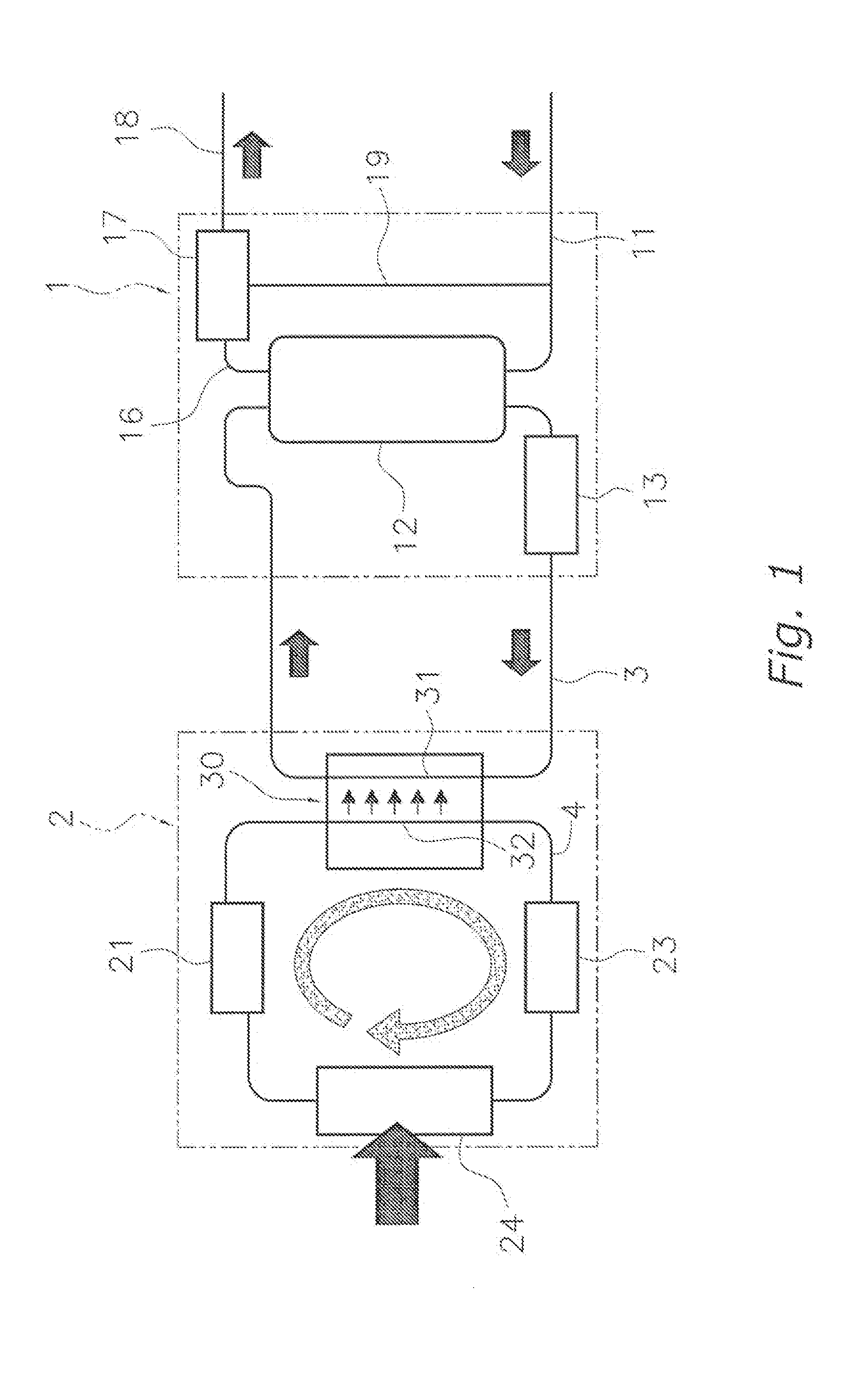
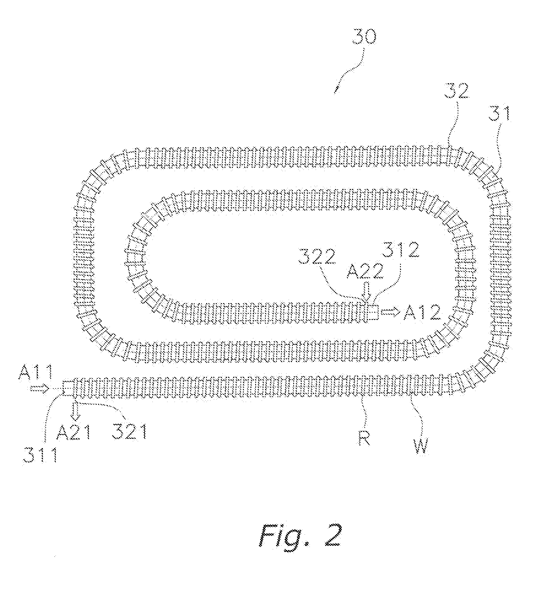
TECHNICAL FIELD[0001]The present invention relates to hot water heater technology. More specifically, the present invention relates to a hot water corrugated heat transfer tube in which the Reynolds number Re of a fluid flowing inside the tube is less than 7,000.BACKGROUND ART[0002]Heat exchangers used in air conditioners, hot water heaters, and the like, are provided with a heat transfer tube in which a fluid such as water flows and which exchanges heat due to the temperature differential between the tube interior and exterior. Furthermore, to improve the heat transfer performance of the heat transfer tube, a grooved tube in which grooves are formed on the tube inner surface is used in some cases. In addition, a technology has also been proposed which improves the heat transfer performance by providing projections on the inner surface of the heat transfer tube.[0003]Providing projections inside the heat transfer tube in this manner increases the heat transfer surface area of the he...

Claims


Application Information

Patent Timeline
Patent Type & Authority Applications(United States)
IPC IPC(8): F28F13/00
CPCF28F1/426F28F1/42F28F1/30F28F1/40F28D7/02F28F13/12
Inventor LI, ZHIXINGMENG, JIANNUMATA, MITSUHARUKASAI, KAZUSHIGE
Owner TSINGHUA UNIV
Learn More