
Method and Material for Manufacturing Electrically Conductive Patterns, Including Radio Frequency Identification (RFID) Antennas

a technology of radio frequency identification and pattern manufacturing, applied in the direction of transfer patterning, instruments, chemistry apparatus and processes, etc., can solve the problems of disruption of conductivity, high cost of materials and inks, and exact etching types

Inactive Publication Date: 2009-10-08
K B
View PDF9 Cites 48 Cited by
  • Summary
  • Abstract
  • Description
  • Claims
  • Application Information

AI Technical Summary

Problems solved by technology

This type of etching is exacting and expensive.
These materials and inks are typically expensive and minor manufacturing defects can result in disruptions of conductivity.
However, the process of electroplating a conductive pattern is a relatively slow and expensive process.

Method used


Image

  • Method and Material for Manufacturing Electrically Conductive Patterns, Including Radio Frequency Identification (RFID) Antennas
  • Method and Material for Manufacturing Electrically Conductive Patterns, Including Radio Frequency Identification (RFID) Antennas
  • Method and Material for Manufacturing Electrically Conductive Patterns, Including Radio Frequency Identification (RFID) Antennas

Examples


Embodiment Construction

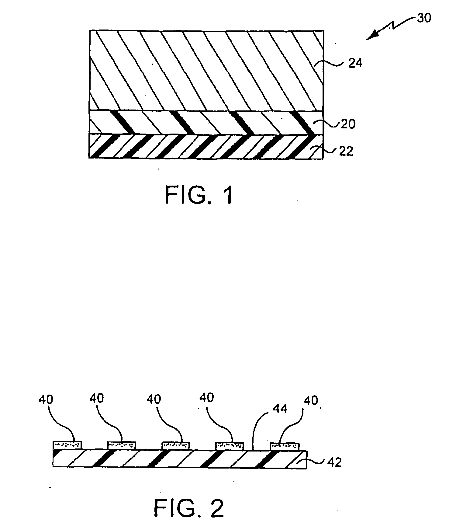
[0027]As shown in FIG. 1, a method of producing an electrically conductive patterned metal film, such as an RFID antenna, includes forming an intermediate structure 30 by applying a layer of release coating 20 to a flexible layer of base polymeric material 22 and depositing a layer of conductive metal 24 over the layer of release coating 20. In one embodiment, the base polymeric material 22 can be polyolefin, such as polyethylene or polyethylene terephthalate (PET), polyester or thermoplastic polyester, such as polycarbonate, polypropylene, biaxially oriented polypropylene (BOPP), polysulfone or a combination thereof. The layer of base polymeric material 22 can be made to any suitable thickness, such as from about 0.1 mil to about 10.0 mil, such as about 0.6 mil, or from about 10 gauge to about 100 gauge.

[0028]Referring again to FIG. 1, the layer of release coating 20 is formulated to have a greater adhesion to the base polymeric material 22 than to the conductive metal 24 that is d...


PUM


Abstract

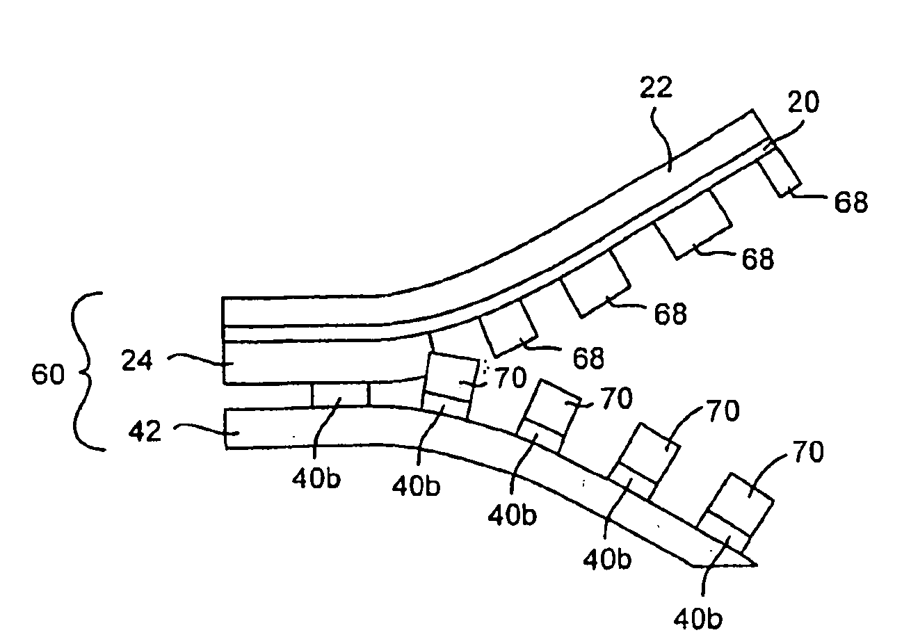
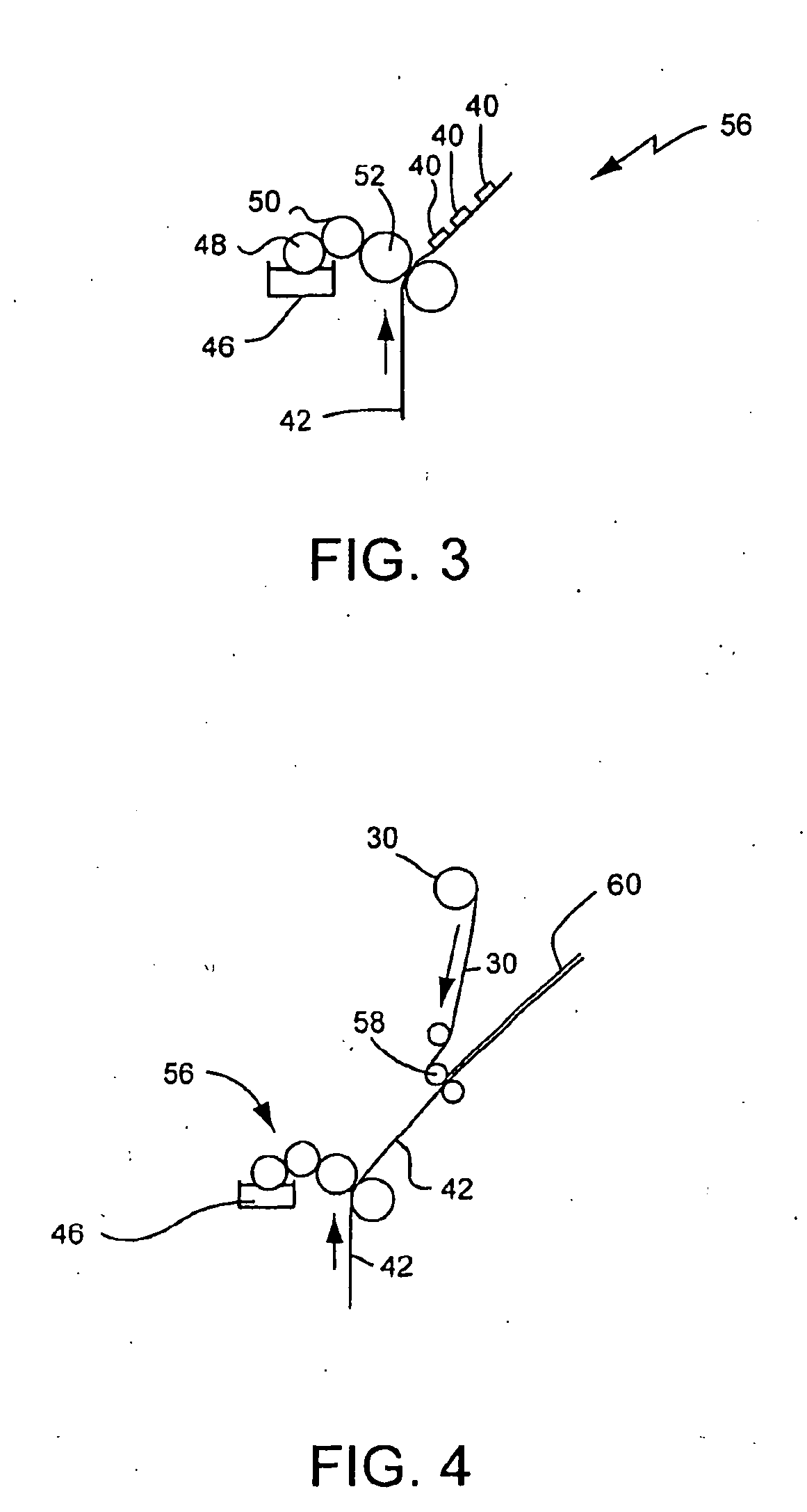
A method of making an electrically conductive patterned film (74), such as an RFID antenna, is disclosed. The method includes the steps of providing a layer of conductive metal (24) adjacent a layer of release coating (20); providing a patterned adhesive layer (400) adjacent a target substrate (42); contacting the layer of conductive metal (24) and the patterned adhesive layer (40), such that a corresponding portion (70) of the layer of conductive metal (24) contacts the patterned adhesive layer (40); and the patterned adhesive layer (40) stripping the corresponding portion (70) of the layer of conductive metal (24) from the release coating (20). The patterned adhesive layer (40) can be formed in the shape of an RFID antenna. An electrical component or a computer chip (80) can be directly applied to the layer of conductive metal (24). An RFID device, such as an RFID tag or label is also disclosed.

Description

BACKGROUND OF THE INVENTION[0001]1. Field of the Invention[0002]The present invention relates to electrically conductive patterns and, more particularly, to radio frequency identification (RFID) antennas.[0003]2. Description of Related Art[0004]RFID devices, such as tags and labels having RFID antennas thereon, are currently being used to track a wide variety of products and files. RFID devices are beginning to be used in a number of industries to track an item using a unique identification code throughout the entire supply chain. For example, RFID devices are being used by an increasingly large number of companies and governmental agencies in conjunction with security systems for controlling accesses and tracking inventory within the supply chain.[0005]As described above, RFID devices are typically recognized as labels or tags. An RFID label can be attached with adhesive directly to the product or in conjunction with a pressure sensitive label. An RFID tag may also be secured to pr...

Claims


Application Information

Patent Timeline
IPC IPC(8): G06K19/077B32B37/02
CPCG06K19/07749H01Q1/22H05K2203/0528H05K3/046H05K2203/0522H01Q1/2225G06K19/077H01Q1/24
Inventor WILLIAMS, RICHARD K.PHILIP, CHARLES R.
Owner K B
Learn More