Back illumination method for counter measuring IR guided missiles

a counter-measured missile and back illumination technology, applied in the field of countermeasure techniques, can solve the problems of not being particularly effective in off-axis illumination of the missile's seeker, commercial aircraft and other aircraft, and being particularly vulnerable to shoulder-launched missiles, etc., to eliminate passengers' perceptive problems, immediately deploy, and cost-effective

Active Publication Date: 2009-10-08
BAE SYST INFORMATION & ELECTRONICS SYST INTERGRATION INC
View PDF44 Cites 22 Cited by
  • Summary
  • Abstract
  • Description
  • Claims
  • Application Information

AI Technical Summary

Benefits of technology

[0025]The subject system completely eliminates the utilization of on-board jamming systems such as LAMP based systems, internal DIRCM based systems, pod-mounted DIRCM based systems, flares, pre-emptive IR chaff, false target generation and towed decoy type systems.
[0026]It will be appreciated that providing an off-aircraft laser jamming system is both cost effective, eliminates perceptive problems for passengers and can be instantly deployed by merely deploying the DIRCM on the ground.

Problems solved by technology

Commercial aircraft and other aircraft which do not active jamming systems such as the directed infrared countermeasure systems, are particularly vulnerable to shoulder-launched missiles especially when the aircraft descends below 10,000 feet, currently the effective maximum altitude for such missiles.
Off-axis illumination of the missile's seeker was found not to be particularly effective.
The problem however in providing commercial aircraft with DIRCMs is both a perceptional problem from the point of view of the passengers and also a cost problem.
Moreover, there is a problem of retrofitting the many existing commercial aircraft even if cost is not an issue.
Note also that the current cost of the DIRCM hardware is on the order of one million dollars, with the cost of retrofitting the aircraft being an additional one million dollars.
If cost where not enough of a deterrent for commercial aviation, the provision of a pod on a commercial aircraft is clearly visible by passengers and is frightening to them.
This impediment in addition to having implications for drag, fuel efficiency and logistics presents a challenge.
Thus having the infrared countermeasure pod visible creates passenger anxiety.
Also having a large crew required for maintenance, testing and boresighting at each turn around for the plane results in a small army of people descending on the plane to ready the DIRCM for the flight, likewise an anxiety producing experience.
As can be seen, both the perceptual problem and the cost of modifying the aircraft, the cost of logistics, the cost of servicing and the cost of system calibration does not provide ready feasibility for aircraft-carried DIRCM type systems.
However, the LAMP-based systems do not cover the required infrared band necessary for jamming modern missile seekers.
However, utilizing flares over a populated area is impractical because the flares can start fires.
Thus flare type countermeasures are not acceptable in an urban environment.
However, every time an aircraft is to descend below 10,000 feet to land the idea of dumping hot metal out of the tail of the aircraft is unacceptable especially over populated areas.
While analysis supports the fact that an aircraft can survive a missile hitting the wing, while the aircraft might survive, the airline industry could not advocate such a solution.
However, the cost and complexity of such a system is a deterrent for such an application; and one cannot conceive of landing a plane towing a radiator behind it.

Method used


Image

  • Back illumination method for counter measuring IR guided missiles
  • Back illumination method for counter measuring IR guided missiles
  • Back illumination method for counter measuring IR guided missiles

Examples


Embodiment Construction

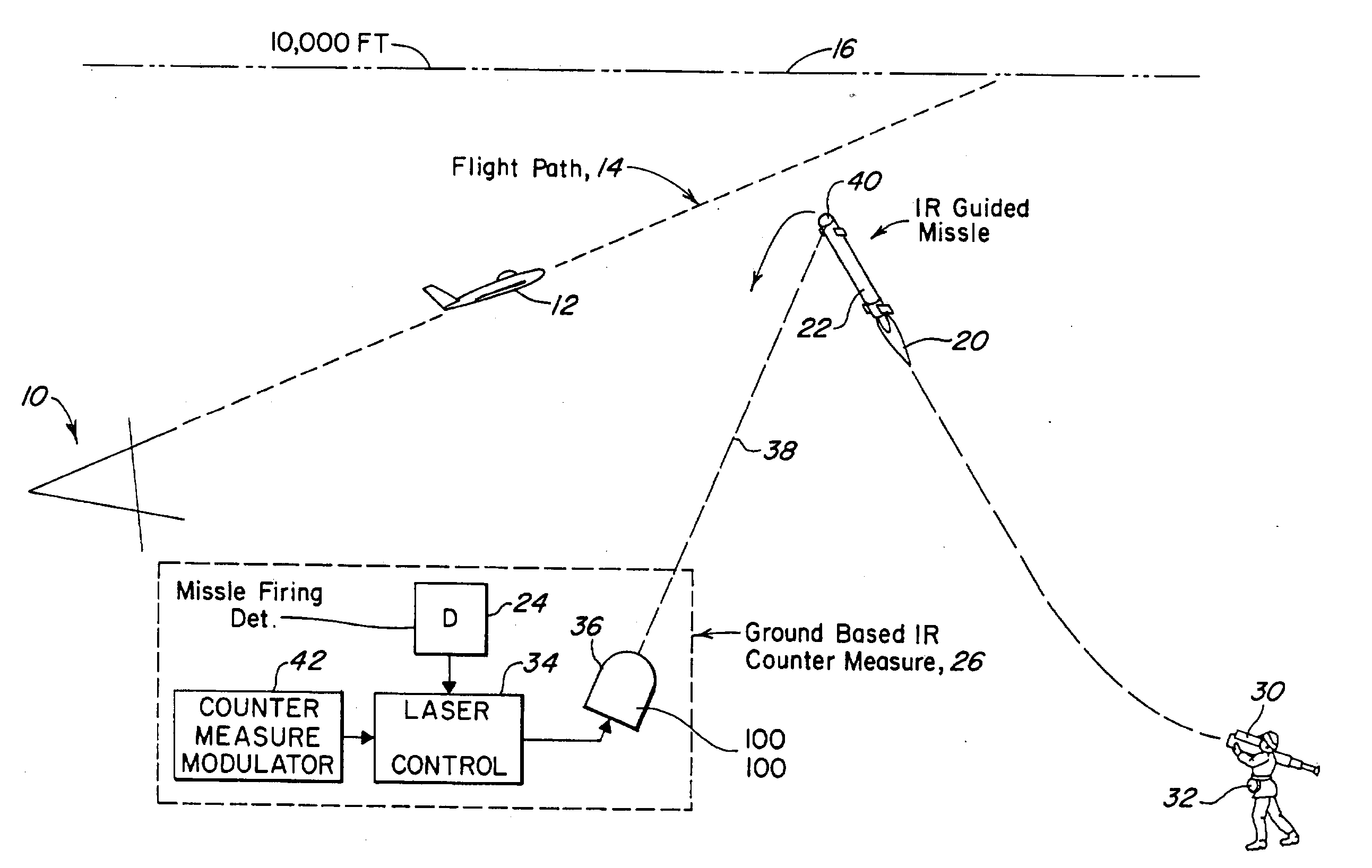
[0038]Referring now to FIG. 1, in a typical airfield scenario for about an airfield 10, an aircraft 12 is shown taking off along a flight path 14 until such time as it reaches an altitude of 10,000 feet as illustrated by dotted line 16. It is noted that for most shouldered-launched IR guided missiles, their altitude limit is approximately 10,000 feet.

[0039]In order to countermeasure an infrared guided missile the subject system, the plume 20 from an IR guided missile 22 is detected by a detector 24 associated with a ground-based IR countermeasure jamming pod 26. The detector may either be an infrared detector or an ultraviolet detector, or may be any detector which detects the deployment of any such missiles. As can be seen, the missile is shown as being shoulder-launched at 30 by an individual 32 who aims the missile 22 in the direction of the aircraft target sought to be destroyed.

[0040]The launching of the missile having been detected by detector 24 activates a laser pointing con...


PUM


Abstract

Commercial aircraft are protected from attack by infrared seeking guided missiles through the utilization of a ground-based directed infrared countermeasure system in which the deployment of an IR guided missile is detected off-aircraft and more particularly on the ground. An infrared laser beam is projected towards the detected missile such that the projected laser infrared radiation impinges upon the missile from the rear. The off-axis infrared radiation illuminates the IR transmissive dome at the head of the missile where it is internally reflected back towards the IR detector carried by the missile through the total internal reflection characteristics of the dome. The domes of these missiles are typically made of a high index of refraction IR transmissive materials such that the material is prone to total internal reflection. The infrared laser generated radiation is a modulated so as to interfere with the guidance system of the missile causing it to execute a turn and plunge to the ground. In one embodiment, the long wavelength infrared laser is a 100-W laser with a beam width of 100 microradians, thus to provide a zone of protection of about three miles.

Description

FIELD OF INVENTION[0001]This invention relates to countermeasure techniques and more particularly to countermeasuring missiles by illuminating the missile from the rear with an appropriately modulated laser beam.BACKGROUND OF THE INVENTION[0002]The wide proliferation of IR missiles both air-air and surface-to-air has led to the military development of a variety of infrared countermeasure systems. This includes such systems as cued IR flares, towed IR decoys, omnidirectional on-board jammers and lamps and laser based directable jammers.[0003]Of these types the only effective jammers for protection of large aircraft against the large inventory of missiles is the directable laser jammer, also known as DIRCM or the Directed Infrared Countermeasure System.[0004]DIRCM systems operate based on a cue from a missile's warning system that slews a pointing and tracking sensor to track the threat missiles and then emits laser jammer radiation onto the missile dome. These systems are co-located ...

Claims


Application Information

Patent Timeline
Patent Type & Authority Applications(United States)
IPC IPC(8): G21G5/00B64D1/04F41H11/02
CPCF41H11/02H04K3/65H04K2203/24H04K3/92H04K2203/14H04K3/825
Inventor CHICKLIS, EVAN P.BARRETT, JOHN L.
Owner BAE SYST INFORMATION & ELECTRONICS SYST INTERGRATION INC
Why Eureka
Try Eureka