Stitching of near-nulled subaperture measurements

a subaperture wavefront and wavefront technology, applied in the direction of measurement devices, structural/machine measurement, instruments, etc., can solve the problems of increasing the range of measurement over which such comparisons are effective, increasing the measurement time, increasing the cost of measurement optics, and increasing the size and numerical aperture. , to achieve the effect of reducing the differences between the test and the shap

Active Publication Date: 2009-10-08
QED TECH INT LLC
View PDF6 Cites 33 Cited by
  • Summary
  • Abstract
  • Description
  • Claims
  • Application Information

AI Technical Summary

Benefits of technology

[0014]The wavefront-measuring gauge can be an interferometer, and, as such, the measurement wavefront can include both a test wavefront and a reference wavefront. The test wavefront propagates into an encounter with the test object and the resulting shape of the test wavefront is compared to the reference wavefront. In situations where the resulting shape of the test wavefront increases fringe density beyond adequately resolvable limits, the variable optical aberrator changes the shape of at least one of the test wavefront and the reference wavefront to systematically reduce differences between the test and reference wavefronts.
[0015]Alternatively, the wavefront-measuring gauge can be a wavefront sensor for measuring a limited range of wavefront shapes. A wavefront generator generates the measurement wavefront in a shape that is within the limited range of wavefront shapes measurable by the wavefront sensor. The measurement wavefront propagates into an encounter with the test object for changing the shape of the measurement wavefront in accordance with a physical characteristic of the test object. The variable optical aberrator changes the shape of the measurement wavefront so that a combined effect of the changes in shape of the measurement wavefront effected by the encounter with the test object and the reshaping of the measurement wavefront by the variable optical aberrator maintains the shape of the measurement wavefront within the limited range of wavefront shapes measurable by the wavefront sensor.
[0016]Another method of practicing the invention involves assembling a composite measurement of a physical test object from a plurality of partially overlapping measurements of the test object. A plurality of partially overlapping data maps measuring a physical property of the test object are acquired from a test wavefront that encounters the test object. Each data map is extracted from a shape of the test wavefront referenced against a datum. The shape of the test wavefront is relatively changed with respect to the datum independently of the test object between acquisitions of a limited number of the data maps to reduce differences between the shape of the test wavefront and the datum. Overlapping regions of the data maps are evaluated to characterize the relative change in the wavefront shape between acquisitions of the data maps. The data maps in are modified in accordance with the characterization of the relative change in the wavefront shape between measurements for assembling the partially overlapping data maps into a composite data map. The composite data map can be displayed or otherwise output as an external representation of the test object.

Problems solved by technology

Various techniques are available for comparing the shape of the test wavefront against the original reference wavefront, such as by forming interference patterns, but the range of measurement over which such comparisons are effective is limited.
Test objects having a form that locally departs more significantly from a spherical form can require a much larger number of subaperture measurements, which can increase measurement time, calculation complexity, noise, and other sources of error.
The cost of the measurement optics generally increases with size and numerical aperture, and large measurement optics can be difficult to manufacture to required accuracy.
While it has been proposed to precisely measure the wavefront modifying optics along with relative motions among the optics required for imparting changes to the test wavefront, applicants have found that differences between the actual and predicted performance of the wavefront modifying optics can introduce systematic errors into the test wavefront.
That is, an over-reliance on the calibration of the wavefront modifying optics can produce specious measurement results, where errors in the departure of the wavefront modifying optics from their expected form are indistinguishable from errors in the departure of the test object from its expected form.
However, similar problems are apparent regarding the required size of the measuring optics and the difficulty of precisely reproducing the desired aspheric wavefronts, especially if the aspheric wavefronts must be adaptable to measuring different aspheric test objects.
Such wavefront modifying optics, which can take the form of spatial light modulators, deformable mirrors, or adjustable lens assemblies, tend to be more complicated than the aspheric test objects intended for measurement, and accurate monitoring of certain dimensions of the wavefront modifying optics is no guarantee that the actual performance of the wavefront modifying optics is free of systematic errors, particularly high-order errors rendered as specious artifacts of the test object.

Method used


Image

  • Stitching of near-nulled subaperture measurements
  • Stitching of near-nulled subaperture measurements
  • Stitching of near-nulled subaperture measurements

Examples


Embodiment Construction

[0037]Preferred embodiments of the invention are directed metrology systems and their methods of use, particularly such systems that synthesize or otherwise assemble subaperture measurements into a composite measurement and to improvements in such systems and methods for measuring aspheric test objects. Significantly, the embodiments provide for increasing the effective range of the subaperture measurements, having the potential for savings in cost and time as well as improvements in measurement accuracy.

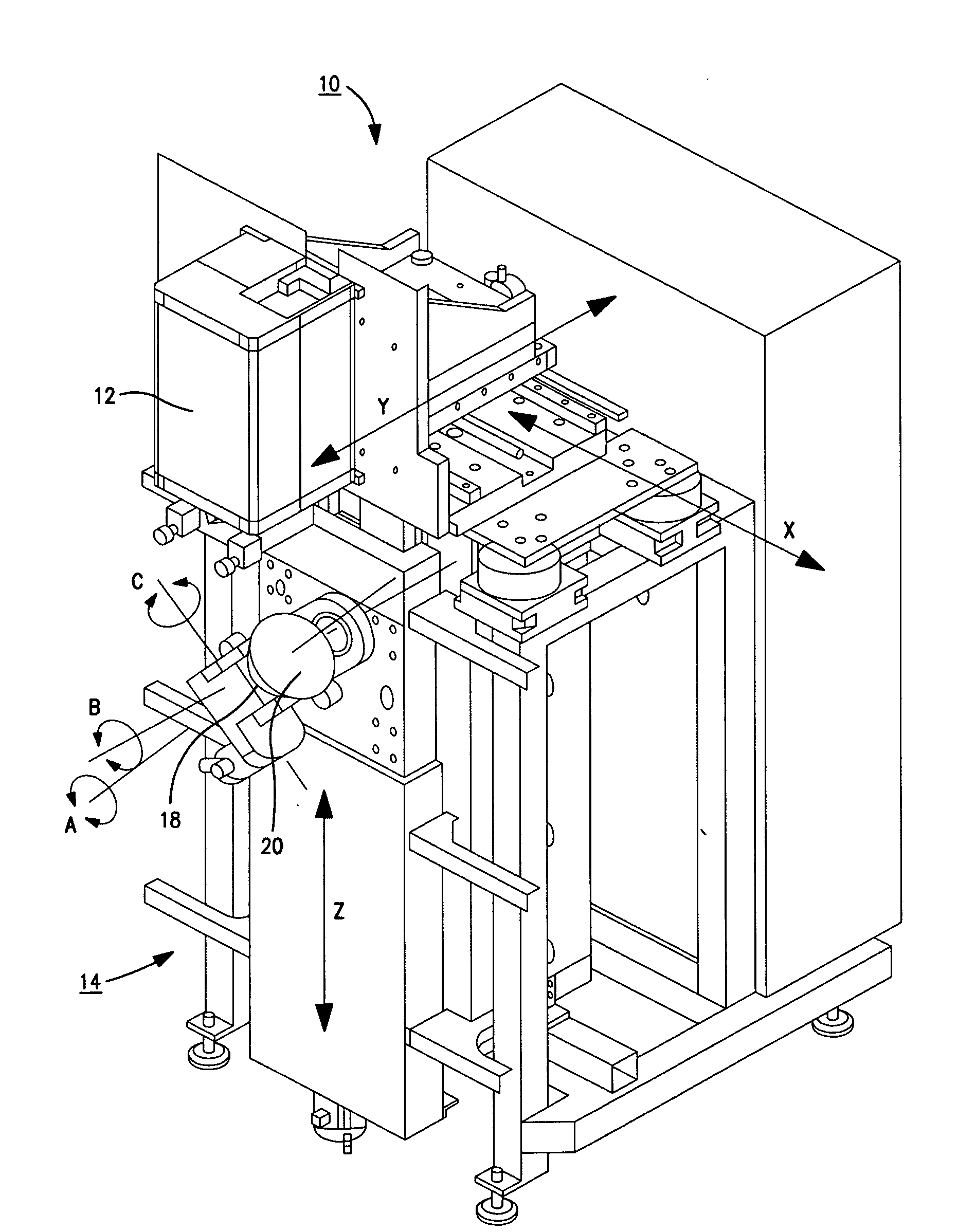
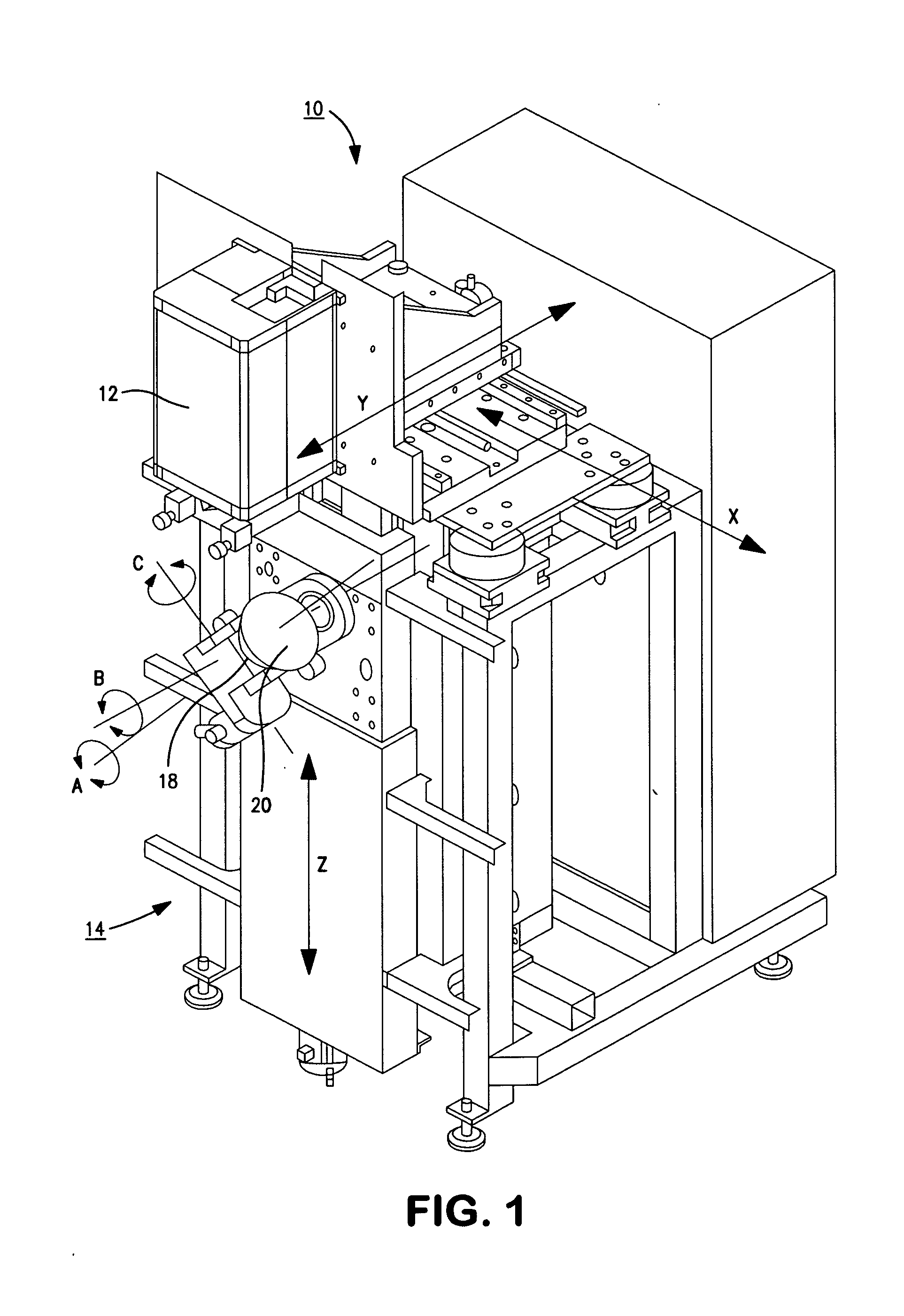
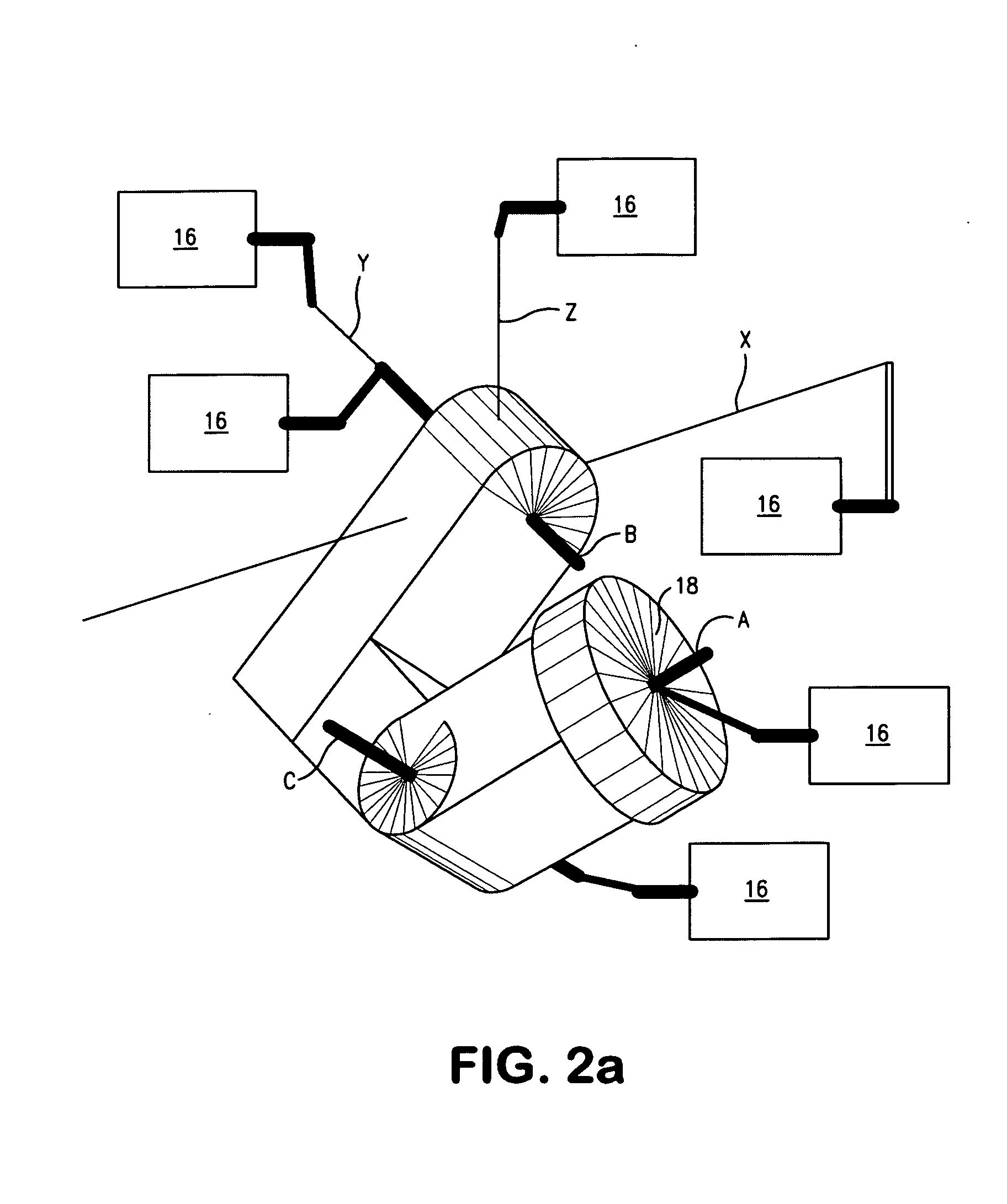
[0038]One example of such a metrology system is shown in FIG. 1. The depicted metrology system 10 includes a wavefront-measuring gauge 12, for example, an interferometer, mounted to (“embedded” in) a multi-axis machine 14 defining a workstation having a chuck or stage 18 for receiving and moving a test object 20 during measurement thereof. The multi-axis machine 14 provides six axes of motion between the wavefront-measuring gauge 12 and the chuck or stage 18 supporting the test obje...


PUM


Abstract

A metrology system for measuring aspheric test objects by subaperture stitching. A wavefront-measuring gauge having a limited capture range of wavefront shapes collects partially overlapping subaperture measurements over the test object. A variable optical aberrator reshapes the measurement wavefront with between a limited number of the measurements to maintain the measurement wavefront within the capture range of the wavefront-measuring gauge. Various error compensators are incorporated into a stitching operation to manage residual errors associated with the use of the variable optical aberrator.

Description

TECHNICAL FIELD[0001]Wavefront measurements provide precise measurements of surface forms or transmission characteristics, particularly of high quality optics. The disclosure relates to systems and methods for subaperture wavefront measurements under near-null conditions for measuring aspheric forms.BACKGROUND OF THE INVENTION[0002]Many optical systems incorporate aspheric optical elements to improve performance or reduce the size or number of optical elements of the systems. Most such aspheric optical elements include surfaces having finite curvatures in orthogonal directions that vary from one another or vary as a function of position. Other aspheric optical elements include finite curvatures in just one direction but the curvatures vary as a function of position. As such, the surfaces of these aspheric optical elements depart from the conventional optical forms of spheres, cylinders, and planes. Yet other aspheric optical elements include refractive indices that similarly vary wi...

Claims


Application Information

Patent Timeline
Patent Type & Authority Applications(United States)
IPC IPC(8): G01B9/02
CPCG01M11/0207G01M11/0257G01B9/02058G01B9/02057G01B9/02039
Inventor MURPHY, PAULDEVRIES, GARYBROPHY, CHRISTOPHERFORBES, GREG
Owner QED TECH INT LLC
Why Eureka
Try Eureka