
Multi-plane cell switch fabric system

Active Publication Date: 2009-10-08
ALAXALA NETWORKS
View PDF11 Cites 17 Cited by
  • Summary
  • Abstract
  • Description
  • Claims
  • Application Information

AI Technical Summary

Benefits of technology

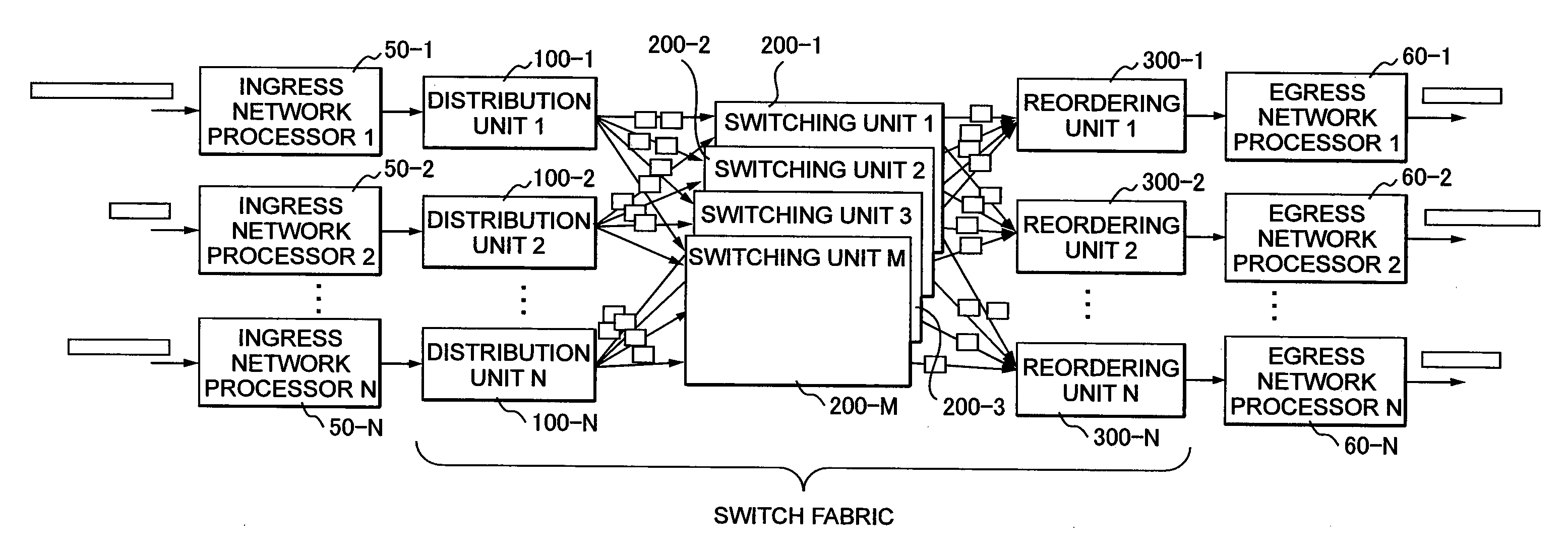
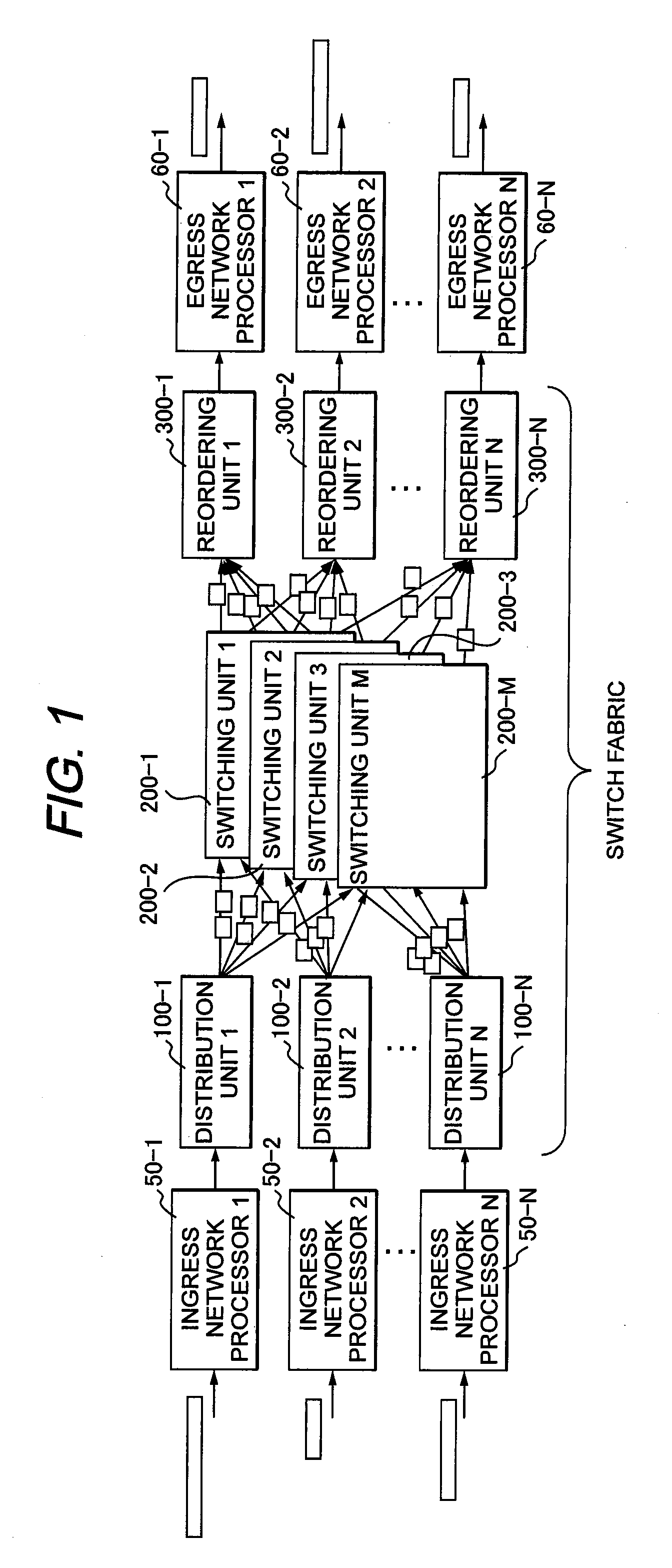
[0010]First of all, as shown in FIG. 1, in a multi-plane switch fabric system that is an object of the present invention, each of N distribution units 100 corresponding to inputs of the switch fabric system distributes and switches variable-length packets to each of the M switching units 200 as they are or distributes and switches cells, which divides the variable-length packets into fixed-length packets, to each of M switching units 200 and each of the M switching units 200 rearranges the cells in the transmitted order and reassembles and outputs the packets or rearranges and outputs the packets in the transmitted order to an address corresponding to one of the N reordering units 300, such that the multi-plane switch fabric system can realize switching with a desired large-capacity line.
[0032]Considering the above-mentioned aspects, the technical problem of the present invention is to provide the switch fabric system that can prevent the decrease of the effective switching capacity of the multi-plane cell switch fabric system switching the variable-length packet.
[0035]With the present invention, even when the variable-length packet is switched, it can suppress the division loss of the switch as well as the division loss of the packet to the minimum requirement. For this reason, the present invention can configure the multi-plane cell switch fabric system that less decreases the effective switching capacity than the method according to the related art.

Problems solved by technology

The problem of the decrease of the switching capacity of the related art can be described attributable to the division loss of the switch and the division loss of the packet.

Method used


Image

  • Multi-plane cell switch fabric system
  • Multi-plane cell switch fabric system
  • Multi-plane cell switch fabric system

Examples


first embodiment

[0052]As a first embodiment, a configuration example of a packet transmission device using a multi-plane switch fabric system is shown in FIG. 1. The packet transmission device includes N ingress network processors 600 (600-1 to 600-N) that analyze variable-length packets for N input lines and provide results of address retrieval, etc., N distribution units 100 (100-1 to 100-N) that receive the variable-length packets attached with the analyzed information and divide and transmit them into fixed-length cells, and M switching units 200 (200-1 to 200-M) each switching the cells independently, N reordering units 300 (300-1 to 300-N) that reassemble the packets from the cells in a transmitted order from the distribution unit 100, and N egress network processors 610 (610-1 to 610-N) that perform header correction, etc., required for the packets (N and M are an integer).

[0053]Among those, a switch fabric system is a part that is configured of the distribution unit 100, the switching unit ...

second embodiment

[0091]The first embodiment 1 describes in detail the method for minimally suppressing both the division loss of the packet and the division loss of the switch in the multi-plane cell switch fabric system. Herein, it may suffice to suppress only the division loss of the switch depending on the line speed or the logic operation frequency that are processed by the switch fabric system. Therefore, a second embodiment 2 will describe a method for minimally suppressing only the division loss of the switch.

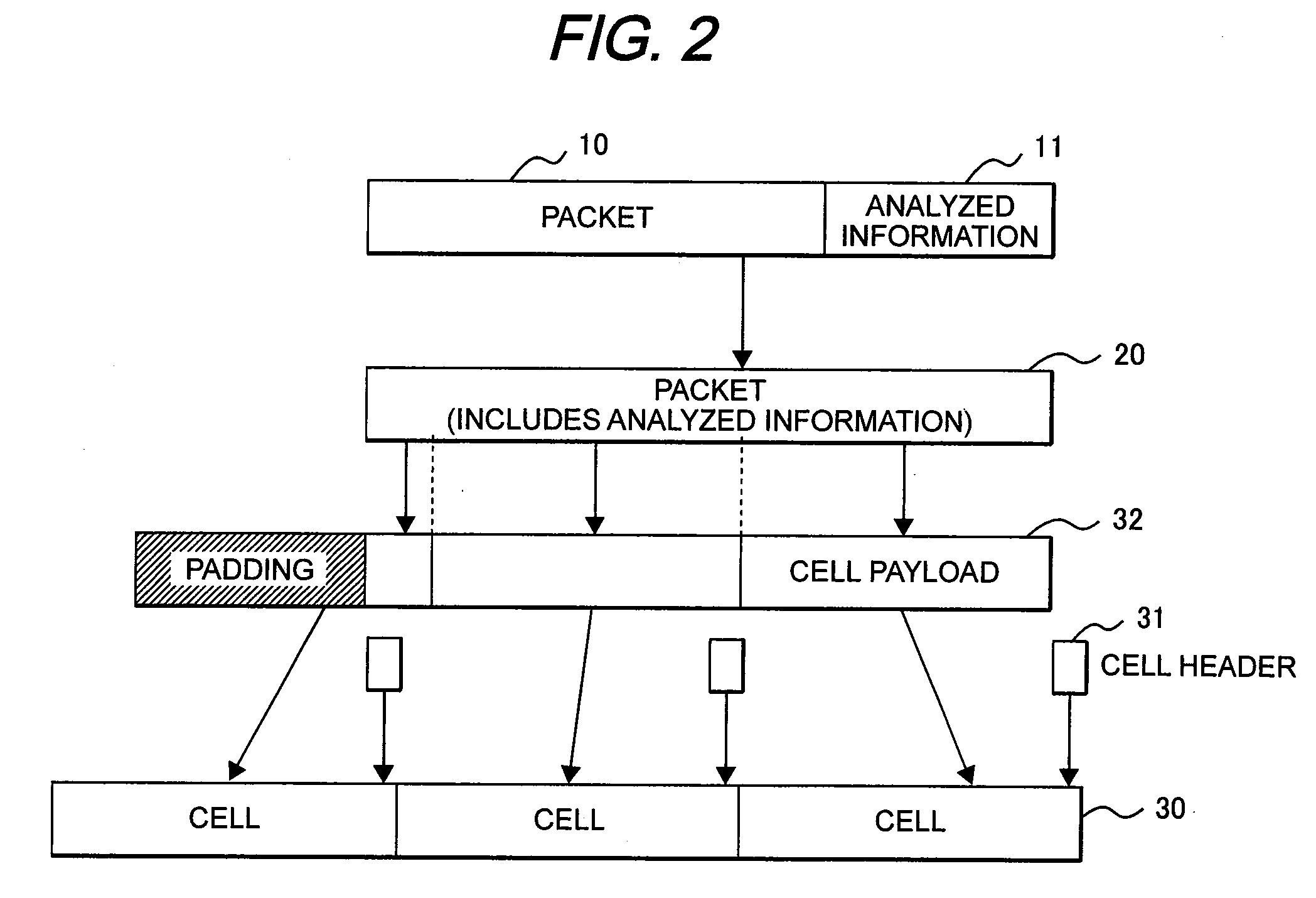
[0092]The second embodiment 2 can be realized by slightly changing the first embodiment. In detail, the first embodiment prevents the division loss of the packet as the cell payload length 411 having a value of the integer multiple being twice or more as large as the packet align length 410. Therefore, if the packet align length 410 and the cell payload length 411 have the same value, the portion of the division loss of the packet described in the first embodiment can be omitted. For exa...


PUM


Abstract

A multi-plane cell switch fabric system prevents a decrease of the effective switching capacity when switching the variable-length packets. Distribution units classify input variable-length packets for each address, arranges the packets by a first division length unit, divides the packets into fixed-length cell payloads by a second division length unit that is an integer multiple being twice or more as large as the first division length unit, and forms a fixed-length cell by providing destination information, a source ID, a sequential number, and packet head tail information to each of the cell payloads. The cells are distributed to all the switching units one by one whenever the cells are collected to be the same number as the plural switching units. The reordering units classify the cells, reorder the sequential number in an original order, and reassemble the packets by the packet head tail information of the cell.

Description

CLAIM OF PRIORITY[0001]The present application claims priority from Japanese patent application JP2008-096016 filed on Apr. 2, 2008, the content of which is hereby incorporated by reference into this application.BACKGROUND OF THE INVENTION[0002]1. Field of the Invention[0003]The present invention relates to a switch fabric system used in a packet switching device, and in particular, to a technology that effectively prevents switching capacity of plural switches operating separately from each other from decreasing.[0004]2. Description of the Related Art[0005]In a network transmission device such as a router, a switch fabric system is used to switch a variable-length packet data between functional blocks in the device. As a switching unit in one method for performing switching of a large-capacity line (high-speed line), there is a multi-plane cell switch fabric system (parallel switch) that includes M switch LSIs including a port of a speed of 1 / M with respect to a required line speed...

Claims


Application Information

Patent Timeline
IPC IPC(8): H04L12/56H04L12/931H04L12/939
CPCH04L49/3072H04L49/1523
Inventor OKUNO, MICHITAKAYAMAMOTO, MITSUOKIMURA, ISAO
Owner ALAXALA NETWORKS
Learn More