
Axial void fraction distribution measurement method and neutron multiplication factor evaluating method

a technology of axial void fraction and measurement method, which is applied in the direction of instruments, greenhouse gas reduction, optical radiation measurement, etc., can solve the problems of not being able to apply the above-described technique to an operating nuclear reactor, not being able to make a report on an actual measurement of the void fraction distribution in the core of a commercial bwr, and not being able to achieve the effect of actual measurement of the void fraction distribution in an operating commercial nuclear reactor

Inactive Publication Date: 2009-10-08
KK TOSHIBA
View PDF1 Cites 2 Cited by
  • Summary
  • Abstract
  • Description
  • Claims
  • Application Information

AI Technical Summary

Benefits of technology

The present invention provides methods for evaluating the axial void fraction distribution and the neutron multiplication factor of a fuel assembly irradiated in a nuclear reactor. The methods involve measuring the intensity of radioactive rays emitted from nuclides at an axial position of the fuel, and comparing it to the intensity of the same radioactive rays emitted from a reference position. The methods also involve calculating the exponential constant used in evaluating the void fraction distribution and the correlation curve between the void fraction and the radioactive ray intensity. These methods can provide more accurate and reliable data for evaluating the performance of the fuel assembly in a nuclear reactor.

Problems solved by technology

However, no report has been made on an actual measurement of the void fraction distribution in the core of a commercial BWR because of lack of feasible measurement technique.
The above-described technique is hard to apply to an operating nuclear reactor, because it employs Cd having a low melting point that might harm structure materials of the operating reactor.
As described above, while the axial void fraction distribution is very important for a BWR, no technique has been available for actual measurement of an axial void fraction distribution in an operating commercial nuclear reactor.

Method used


Image

  • Axial void fraction distribution measurement method and neutron multiplication factor evaluating method
  • Axial void fraction distribution measurement method and neutron multiplication factor evaluating method
  • Axial void fraction distribution measurement method and neutron multiplication factor evaluating method

Examples


first embodiment

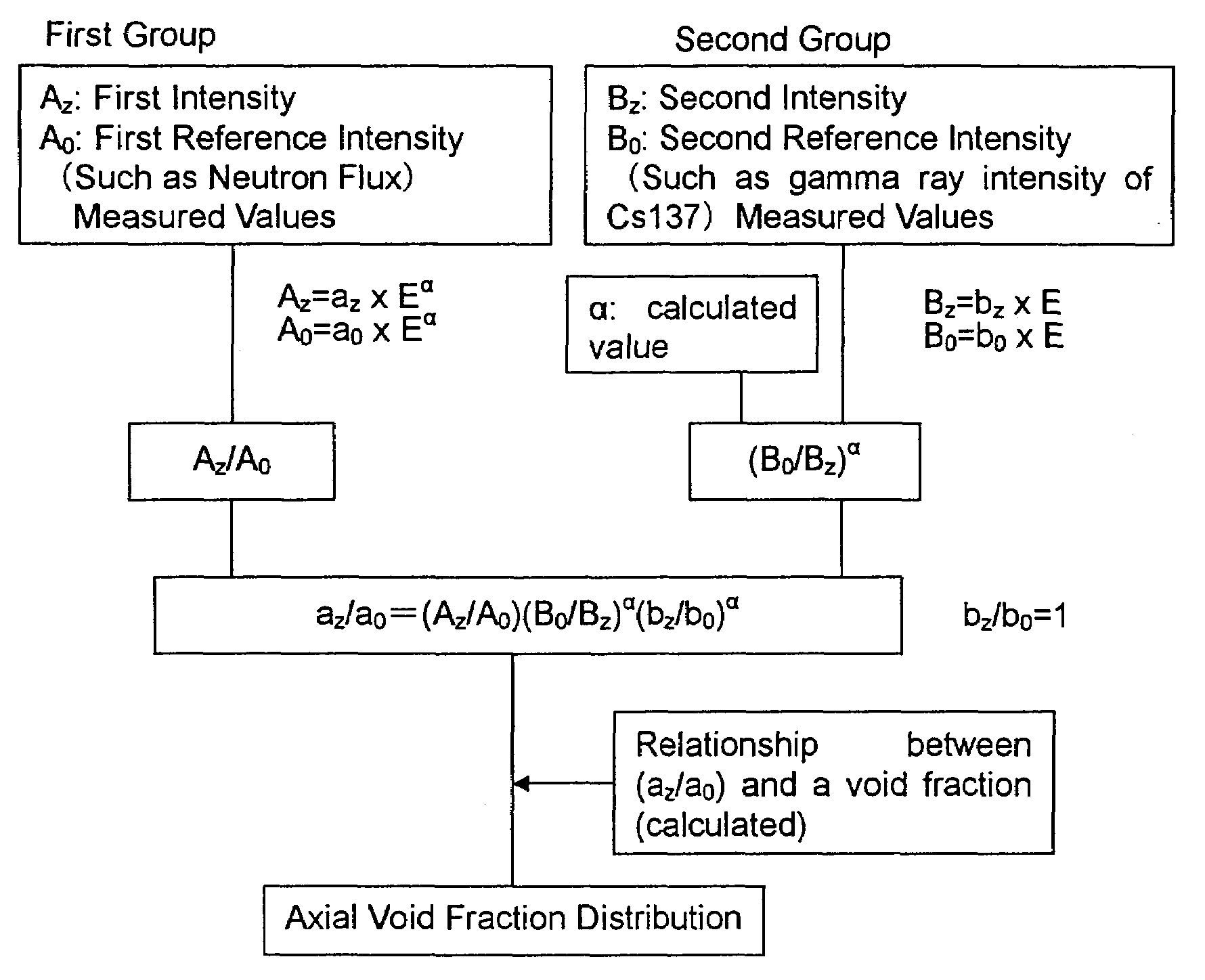
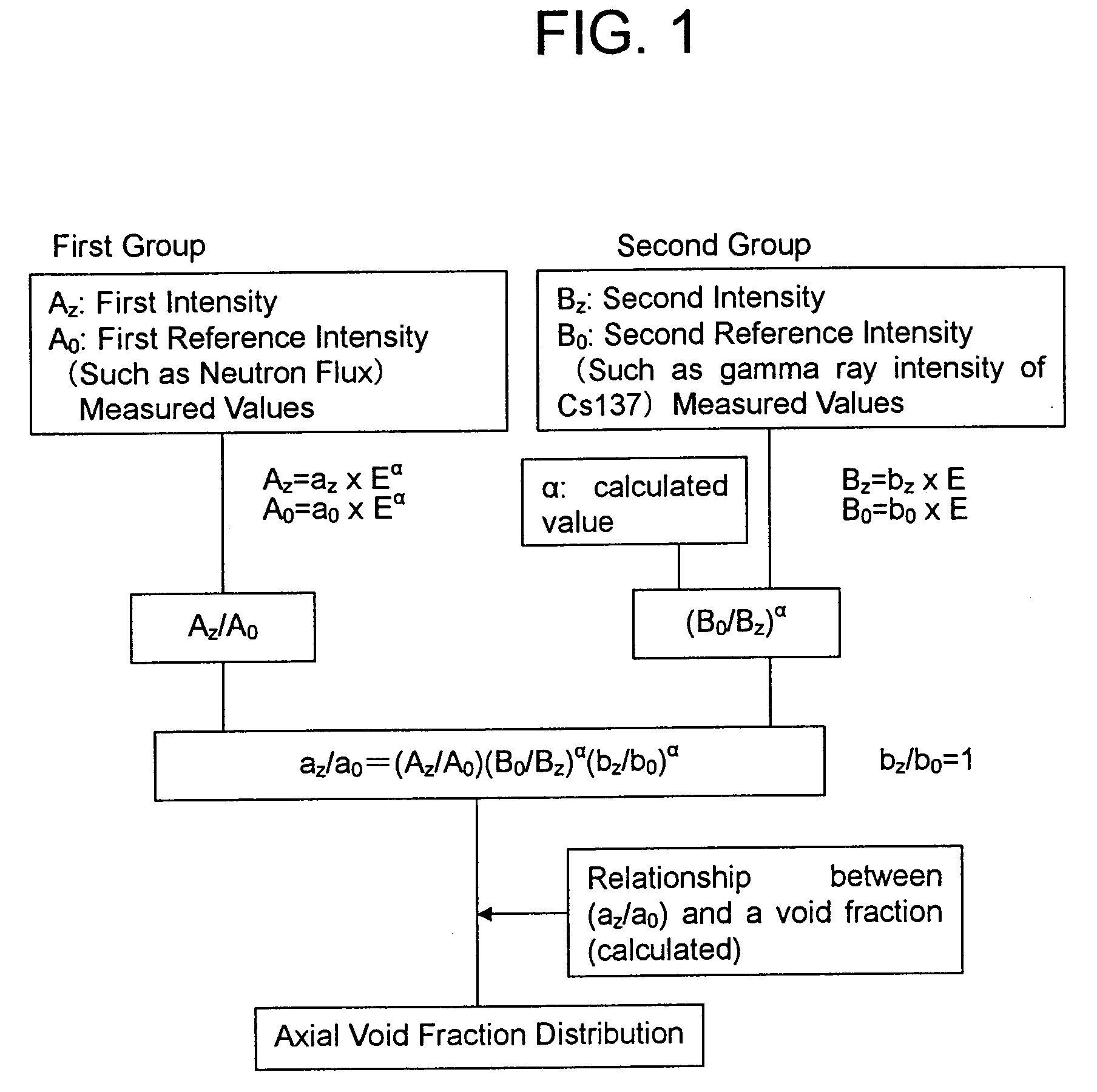
[0110]FIG. 1 is a flow chart of an axial void fraction distribution measurement method according to the first embodiment of the present invention.

[0111]In this embodiment, as the first intensity Az, a neutron emission rate Sz and S0 expressed as Sz=az×Eα or S0=a0×Eα is used. And as the second intensity Bz and B0, gamma ray intensity γaz and γ0 expressed as γz=gz×Eα or γ0=g0×Eα is used.

[0112]Then, the ratio (az / a0) is expressed as;

(az / a0)=(Sz / S0)(γ0 / γz)α(gz / g0)α.

[0113]Based on the value of (az / a0) and the relationship between (az / a0) and a void fraction evaluated otherwise, a void fraction of the fuel is evaluated.

[0114]Also a correlation function representing a relationship between (az / a0) and a void fraction is derived from computations. The void fraction experienced at each axial position of the fuel assembly, i.e., the void fraction distribution is obtained from this correlation function and (az / a0) derived from the first and second intensities of the radioactive rays.

[0115]Usual...

second embodiment

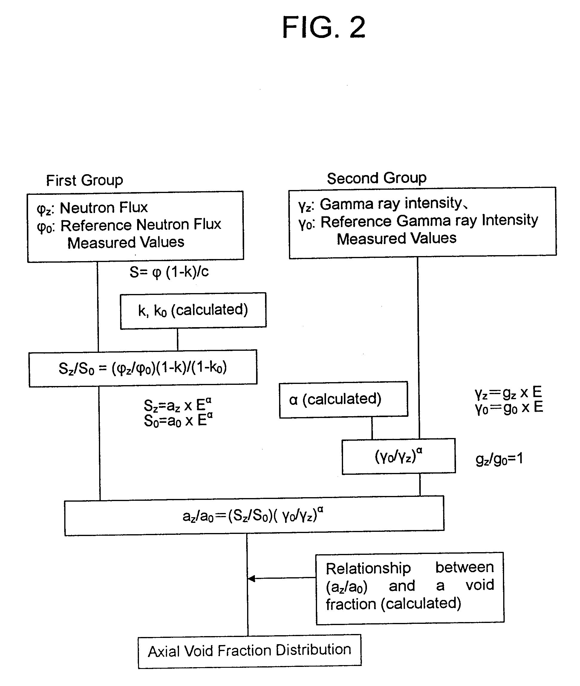
[0119]FIG. 2 is a flow chart of an axial void fraction distribution evaluation method according to the second embodiment of the present invention.

[0120]This embodiment is different from the first embodiment in a point that the values of (φz / φ0) are corrected for the contribution of the axial variation of the neutron multiplication factor by a standard neutron multiplication factor distribution obtained from the design calculations.

[0121]As described above, the effect is rather small relative to (φz / φ0−1) in a BWR fuel assembly so that no problem arises even if the value obtained by the design calculation is used, because the effect of the neutron multiplication factor is about 10 to 20%. It is well known that the neutron flux or neutron counting rate (φ) has a relationship of φ=c S / (1−k), where k is a neutron multiplication factor, S is a neutron emission rate, and c is a proportionality constant. This relation is used in this embodiment.

[0122]The proportionality constant (c) can be...

third embodiment

[0123]FIG. 3 is a flow chart of an axial void fraction distribution evaluation method according to the third embodiment of the present invention.

[0124]A difference of this embodiment from the second embodiment is that (φz / φ0) is corrected for the contribution of an axial variation of the neutron multiplication factor based on a fuel assembly averaged exposure that seems to be available most easily from the operator of the reactor.

[0125]This method of determining a neutron multiplication factor (k) comprising the steps of correcting an estimated void fraction distribution by measured values repeatedly, determining the infinite multiplication factor (k∞) that depends on the exposure and corresponds to the void fraction, and then determining k.

[0126]The procedure of this embodiment is described in detail below.

[0127]An axial neutron flux (or the axial neutron counting rate) distribution and a gamma ray intensity distribution, as well as (γ0 / γz)α can be determined as described for the f...


PUM


Abstract

A first intensity Az expressed as Az=az×Eα, a first reference intensity A0 expressed as A0=a0×Eα, a second intensity Bz expressed as Bz=bz×E, and a second reference intensity B0=b0×E, are evaluated. The first intensity and the first reference intensity are of radioactive nuclides generated by a neutron capture reaction of a heavy nuclide or a fission product nuclide. The second intensity and the second reference intensity are of radioactive fission product nuclides except nuclides generated by a neutron capture reaction. The reference intensities are measured where the void fraction is known. Also a correlation curve of (az / a0) and a void fraction is evaluated. Finally an axial void fraction distribution is evaluated based on the value of (az / a0) and the correlation curve.

Description

CROSS REFERENCE TO RELATED APPLICATION[0001]This application is based upon and claims the benefit of priority from the prior Japanese Patent Application No. 2005-143884, filed on May 17, 2005; the entire content of which is incorporated herein by reference.BACKGROUND OF THE INVENTION[0002]The present invention relates to a measurement method of an axial void fraction distribution in a core of a boiling water reactor (BWR), and also to an evaluating method of a neutron multiplication factor of a fuel assembly to be contained in a container apparatus.[0003]In a BWR, cooling water is heated and boiled in a reactor core as it flows from the bottom of the core to the top of the core. So, a void fraction that is a ratio of the bubbles to space where the cooling water flows in a channel box, increases as the cooling water flows from the upstream (the bottom of the core) to the downstream (the top of the core).[0004]The void fraction significantly affects core characteristics such as reacti...

Claims


Application Information

Patent Timeline
Patent Type & Authority Applications(United States)
IPC IPC(8): G21C17/00
CPCG21C1/084G21C17/10G21Y2002/201Y02E30/31G21Y2002/304G21Y2004/40G21Y2002/204Y02E30/30
Inventor UEDA, MAKOTOKUMANOMIDO, HIRONORIMITSUHASHI, ISHIKIKUCHI, TSUKASAYOSHIOKA, KENICHISASAKI, TOMOHARUHIRAIWA, KOUJI
Owner KK TOSHIBA
Learn More