Upper Plenum Structure of Cooled Pressure Vessel for Prismatic Very High Temperature Reactor

a very high temperature, cooled pressure vessel technology, applied in the direction of reactor fuel susbtance, nuclear elements, greenhouse gas reduction, etc., can solve the problems of no detailed structural design on how to make the necessary structure, high-chrome steel has never been used in the pressure vessel, etc., to achieve the effect of maximizing utilization in the industry

Inactive Publication Date: 2009-10-08
KOREA ATOMIC ENERGY RES INST +1
View PDF2 Cites 20 Cited by
  • Summary
  • Abstract
  • Description
  • Claims
  • Application Information

AI Technical Summary

Benefits of technology

[0028]The present invention is a useful invention with an advantage of enabling an internal flow channel design to prevent the high-temperature inlet coolant from contacting with the pressure vessel by providing the detailed structural design of the upper plenum for the prismatic very high temperature reactor and also is expected to have huge utilization in the industry.

Problems solved by technology

However, high-chrome steel has never been used in the pressure vessel of a commercial nuclear reactor and there are many challenges with the supply and the production of this material.
Therefore, there is a problem with the application in a middle / short period of time.
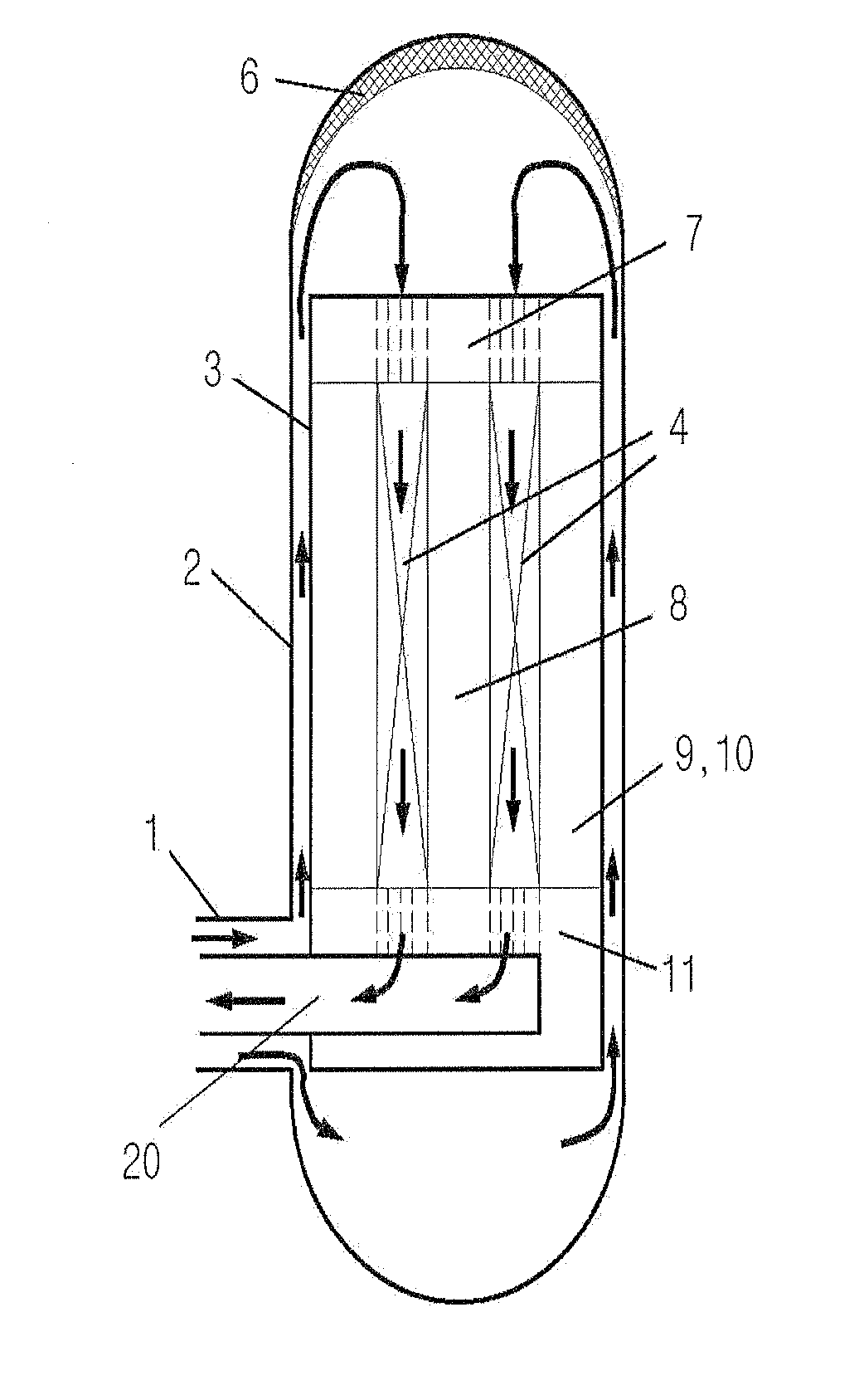
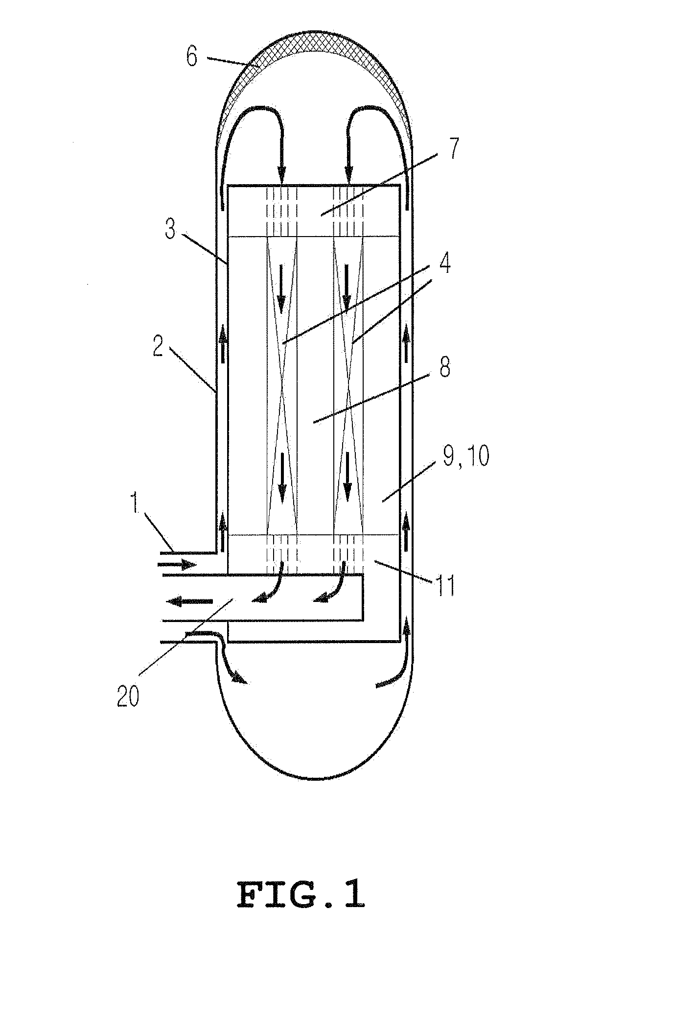
Although the upper plenum plays an important role in the coolant inlet flow path by supplying the coolant transferred from the rising flow channel to the entrance of the core, there has been no detailed structural design on how to make the necessary structure by loading the graphite structure.

Method used


Image

  • Upper Plenum Structure of Cooled Pressure Vessel for Prismatic Very High Temperature Reactor
  • Upper Plenum Structure of Cooled Pressure Vessel for Prismatic Very High Temperature Reactor
  • Upper Plenum Structure of Cooled Pressure Vessel for Prismatic Very High Temperature Reactor

Examples


Embodiment Construction

[0038]The construction and the operation of the present invention will now be described more in detail with reference to the accompanying drawings, in which exemplary embodiments thereof are shown. In the following description of the present invention, a detailed description of known functions and components incorporated herein will be omitted when it may make the subject matter of the present invention rather unclear.

[0039]FIG. 5 is a cross sectional view illustrating an upper plenum in accordance with the present invention; FIG. 6 is a perspective view illustrating coolant distributing blocks in accordance with the present invention; FIG. 7 is a block diagram illustrating the coolant distributing block for an embodiment in accordance with the present invention; and FIG. 8 is a block diagram illustrating the coolant distributing block for another embodiment in accordance with the present invention.

[0040]The present invention constitutes an upper plenum structure 14 as shown in FIG....


PUM


Abstract

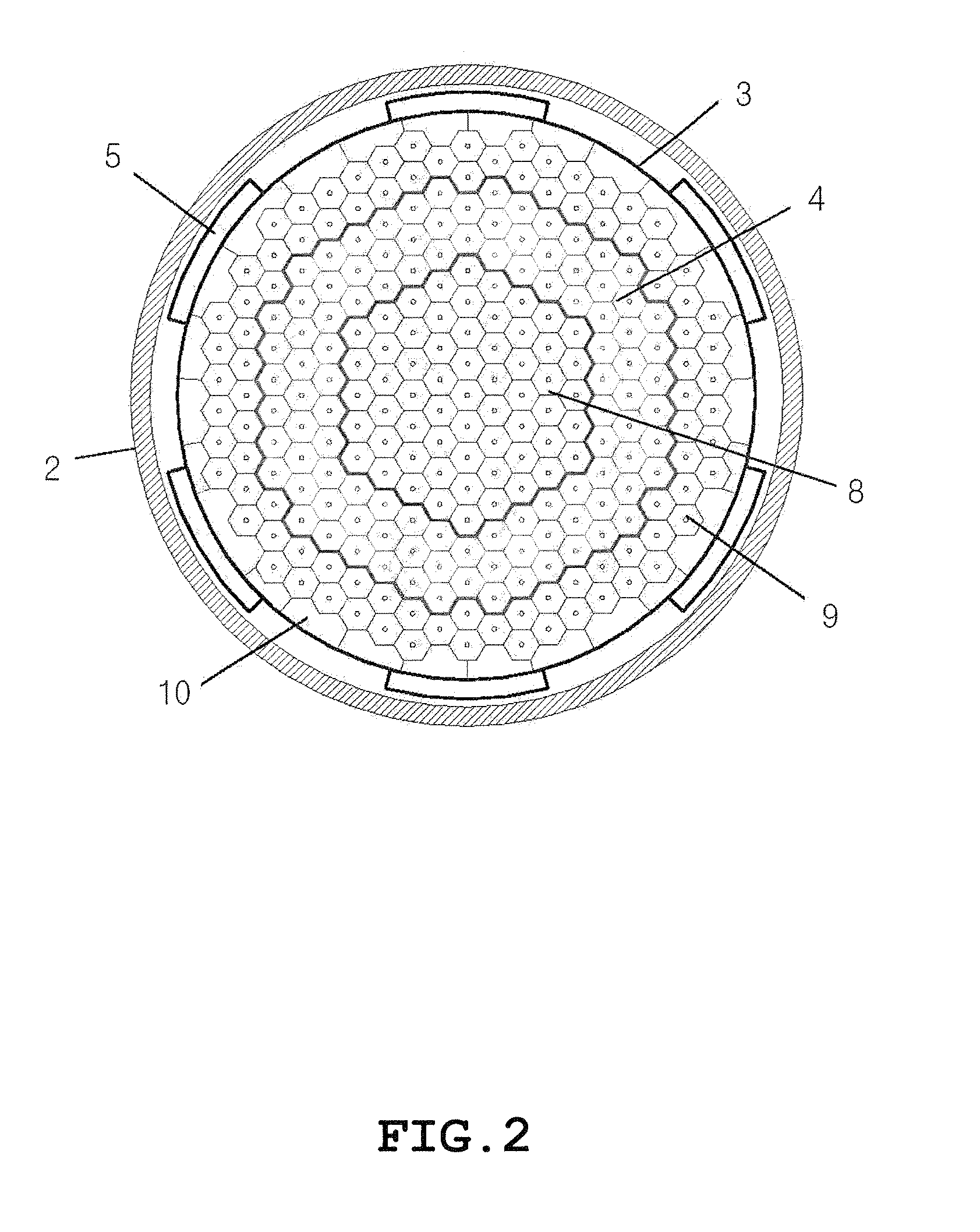
An upper plenum structure of a cooled pressure vessel for a prismatic very high temperature reactor which secures a space for coolant to supply to a core and also supports an upper reflector located inside a graphite structure on top of the core. The upper plenum structure includes a cavity structure where the coolant goes down in the upper plenum structure, a plurality of upper reflector supports formed with the cavity and supporting the upper reflector located on top thereof, and a plurality of coolant distributing blocks. Each of the coolant distributing blocks is coupled with a bottom portion of a respective one of the upper reflector supports and is located on top of the core in order to distribute the coolant collected in a cavity, formed by the upper reflector support, to the core. The coolant distributing blocks cooperate with the upper reflector supports to define the cavity structure.

Description

BACKGROUND OF THE INVENTION[0001]1. Field of the Invention[0002]The present invention relates to an upper plenum structure of a cooled pressure vessel for a prismatic very high temperature reactor, and more particularly, to an upper plenum structure which secures a space for coolant to supply to a core and also supports an upper reflector located inside a graphite structure on top of the core.[0003]2. Description of the Related Art[0004]For a very high temperature (gas) reactor, coated particles of nuclear fuel, layered with thermostable carbon and silicon carbide, are used as fuel; thermo-resistant graphite is used as a moderator and a structural frame of a pressure vessel; and the helium is used as a coolant. For these reasons, a high gas outlet temperature of more than 950° C., which cannot be obtainable in other types of nuclear reactors, can be produced with inherent passive safety by using heat generated from this nuclear reactor. The high temperature generated from this react...

Claims


Application Information

Patent Timeline
Patent Type & Authority Applications(United States)
IPC IPC(8): G21C15/02G21C15/28
CPCG21C1/00G21C11/06Y02E30/40G21C15/22Y02E30/30G21C15/02F17C1/00F17C3/10
Inventor KIM, MIN-HWANLIM, HONG-SIKKIM, DONG-OKCHANG, JONG-HWALEE, WON-JAE
Owner KOREA ATOMIC ENERGY RES INST
Why Eureka
Try Eureka