
Electrical Battery Comprising Flexible Generating Elements and a System for the Mechanical and Thermal Conditioning of Said Elements

Inactive Publication Date: 2009-10-08
DOW KOKAM FRANCE
View PDF34 Cites 44 Cited by
  • Summary
  • Abstract
  • Description
  • Claims
  • Application Information

AI Technical Summary

Benefits of technology

[0016]The invention aims to improve the prior art by proposing an electrical battery that combines the advantages of the use of generating elements with a flexible element with a mechanical and thermal packaging system that improves the service life and safety of the battery both from the point of view of electrochemical behaviour and vis-a-vis current constraints in the automotive industry, and particular those concerning crashes.

Problems solved by technology

However, when these elements are charged and discharged, the result is a production of heat which, when it is not controlled, may have the effect of reducing the service life of the elements, or even giving rise, under extreme conditions, to risks of thermal runaway for certain chemical components of elements, leading to deterioration of the battery.
This type of packaging has certain drawbacks, including high manufacturing costs as well as the need to electrically insulate at least one of the electrodes of the metal cup and to add discharge valves for releasing the pressure in the event of overcharging or overheating of an element.
However, with such an envelope, the mechanical strength of the elements is significantly weakened, which runs counter to the current constraints in the automotive industry, in particular relating to crashes.
In addition, the stack is then liable to deform, in particular with movements of the layers with respect to one another.
The result of these movements is variations in the contact resistances between said layers, said variations producing additional heating that may lead to premature aging, a limitation to the energy available and risks of triggering of thermal runaway.

Method used


Image

  • Electrical Battery Comprising Flexible Generating Elements and a System for the Mechanical and Thermal Conditioning of Said Elements
  • Electrical Battery Comprising Flexible Generating Elements and a System for the Mechanical and Thermal Conditioning of Said Elements
  • Electrical Battery Comprising Flexible Generating Elements and a System for the Mechanical and Thermal Conditioning of Said Elements

Examples


Embodiment Construction

)

[0033]In the description, the words positioning and space are taken with reference to the positioning of the battery shown in FIG. 1. However, the sealing of the battery makes it possible to envisage its positioning according to a different orientation.

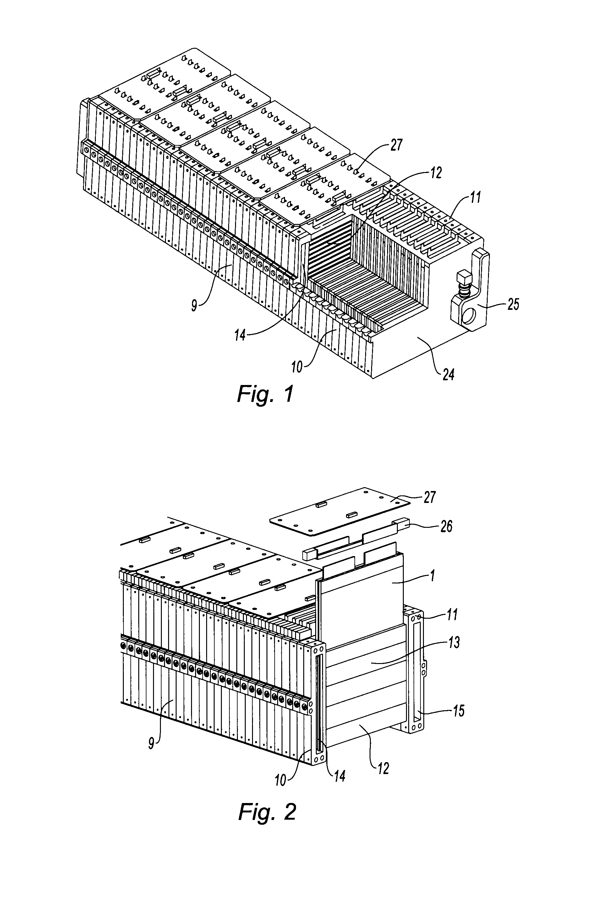
[0034]In relation to the figures, an electrical battery is described below comprising a plurality of electrical energy generating elements 1 formed from at least one electrochemical cell 2 that is packaged in a flexible sealed envelope 3. In particular, the electrochemical cells 2 are of the lithium-ion or lithium-polymer type.

[0035]The battery is more particularly intended to supply a motor vehicle traction electric motor, whether it be a case of an electrical vehicle or of the electrical / thermal hybrid type. However, the battery according to the invention can also find its application for the storage of electrical energy in other transport modes, in particular in aeronautics. Moreover, in stationary applications such as for windmil...


PUM


Abstract

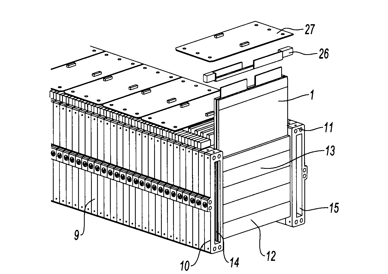
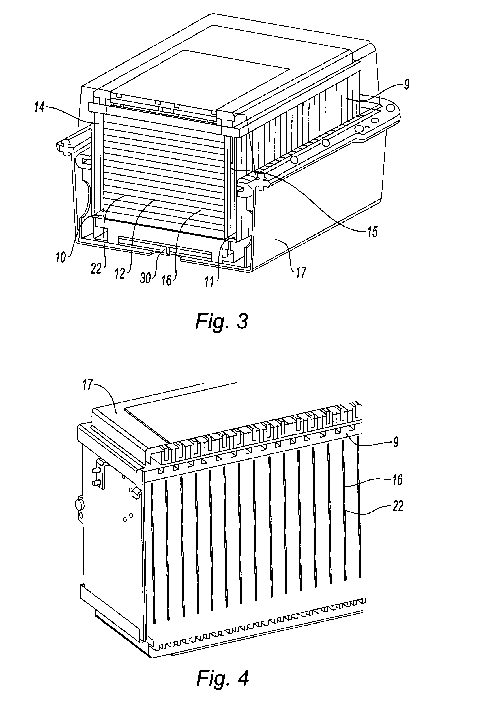
An electrical battery includes a plurality of electrical energy generating elements formed by at least one electrochemical cell that is packaged in a flexible sealed envelope, and a system for the mechanical and thermal conditioning of the elements. The conditioning system forms a structural body made from thermally conductive material. The body has two longitudinal members and a plurality of cross-members connecting the longitudinal members so as to form between the cross-members housings in which respectively a generating element is disposed. The body includes a circulation path for a thermal conditioning fluid. The path has two channels, respectively upstream and downstream, that are formed respectively in a longitudinal member and passages formed in each of the cross-members. The passages are in fluid communication on each side with respectively the upstream channel and the downstream channel.

Description

BACKGROUND[0001](1) Field of the Invention[0002]The invention concerns an electrical battery that is in particular intended for electrical or hybrid motor vehicle traction, that is to say comprising an electric motor driving the driven wheels combined with a thermal engine driving these wheels or possibly other driven wheels.[0003](2) Prior Art[0004]In particular, the invention applies to a high degree of hybridisation of thermal vehicles which may go as far as complete electrification of the traction chain. In this case, the batteries do not then merely serve to assist the vehicles in the acceleration phases but also to provide movement of the vehicle autonomously over greater or lesser distances.[0005]To guarantee the levels of power and energy required for the applications in question, it is necessary to create batteries comprising a plurality of electrical energy generating elements.[0006]However, when these elements are charged and discharged, the result is a production of heat...

Claims


Application Information

Patent Timeline
IPC IPC(8): H01M2/12H01M10/50H01M50/121H01M50/124H01M50/136H01M50/211H01M50/291
CPCB60R16/04H01M10/52H01M2/0262H01M2/0275H01M2/0287H01M2/0292H01M2/1077H01M2/1094H01M2/1241H01M10/4235H01M10/5004H01M10/5032H01M10/5059H01M10/5063H01M10/5075H01M10/5079H01M10/5087H01M2/0245H01M10/647H01M10/6569H01M10/6557H01M10/6567H01M10/6561H01M10/613H01M10/658Y02E60/10H01M50/258H01M50/124H01M50/1245H01M50/24H01M50/3425Y02P70/50H01M50/121H01M50/291H01M50/136H01M50/211
Inventor GABEN, FABIEN
Owner DOW KOKAM FRANCE
Learn More