
Treadmill apparatus

a treadmill and treadmill technology, applied in the field of treadmills, can solve the problems of limited types of exercise equipment suitable, and achieve the effect of reducing spine weight and fatigue, and reducing weigh

Inactive Publication Date: 2009-10-08
MARESH JOSEPH DOUGLAS
View PDF12 Cites 28 Cited by
  • Summary
  • Abstract
  • Description
  • Claims
  • Application Information

AI Technical Summary

Benefits of technology

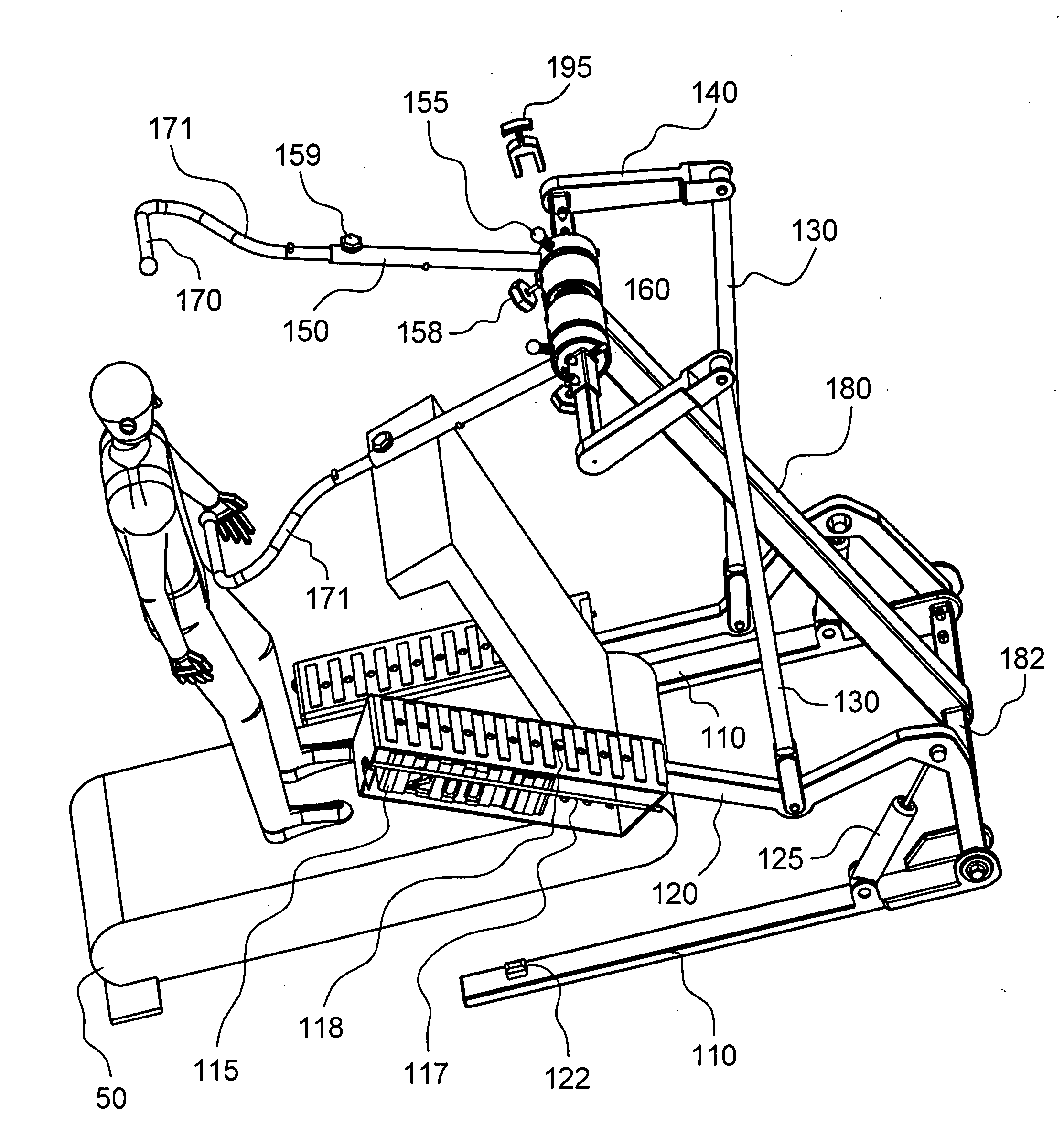
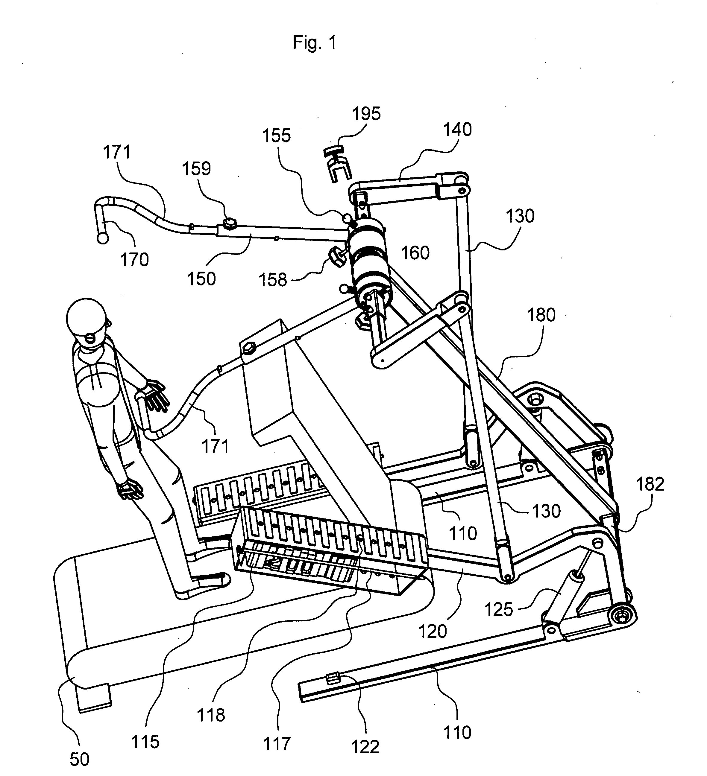
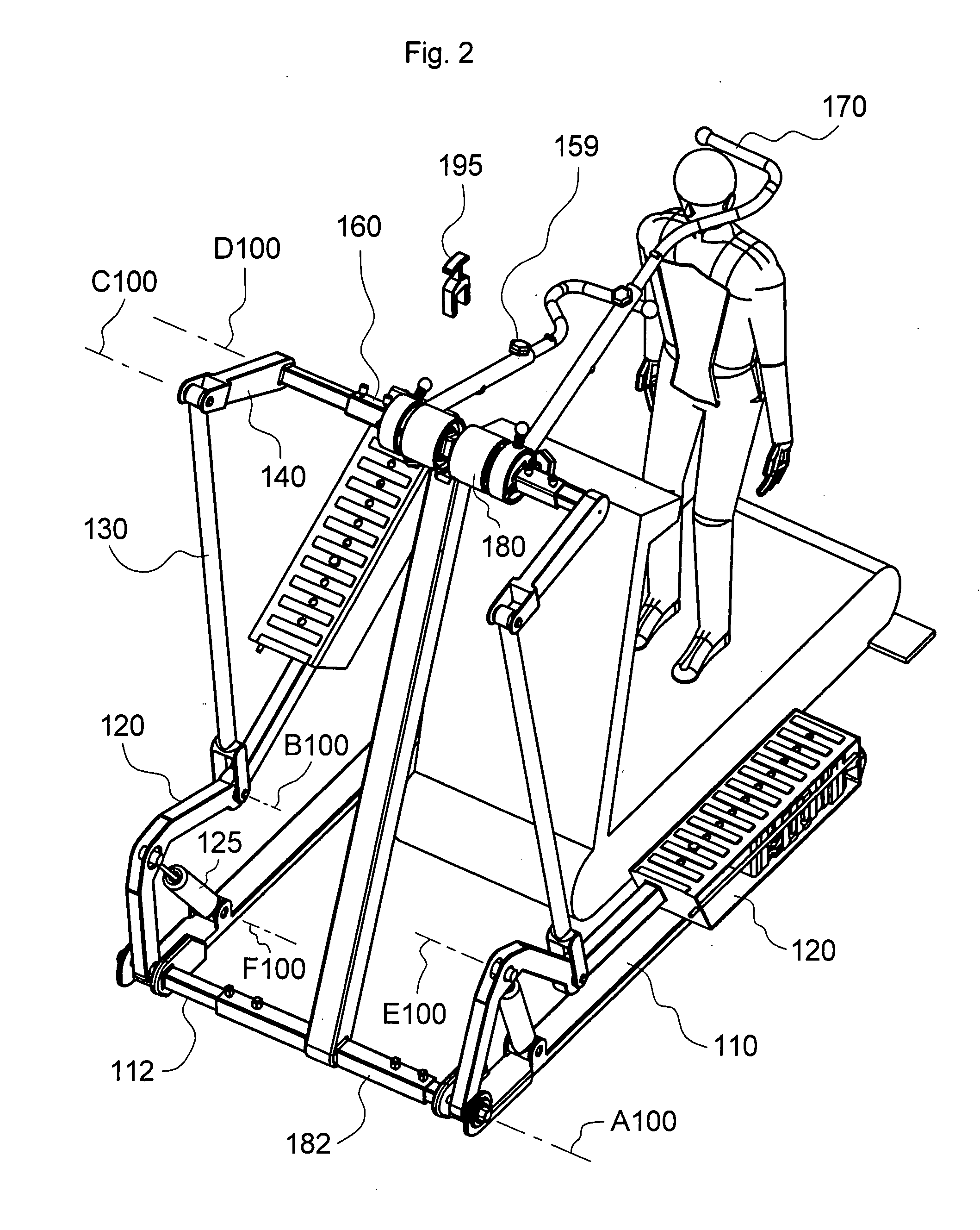
[0004]One of the benefits in utilizing the present invention while simultaneously walking on a treadmill is that the user would be able to have a direct influence on, or effect a change, in the portions of the body that the user wishes to exercise. Furthermore, the user is enabled to reduce spine weight and fatigue at the lower body while the upper body is anxious to exert itself. In such a manner, the constraints imposed at the handle bar allow, for example, the user to grasp said bar, perform a “lat pull-down”, or some form of a lat pull-down, with or without the handle bar(s) being in motion. The dynamics thus available enable the user to perform a wide variety of exercises new in the art. Additionally, an inherent advantage, particularly when walking on a moving surface, is that while grasping the hand grips the user has an instant non visual sense of the user's relative position upon the treadmill belted region, primarily with regard to lateral restraints imposed on said bar. Also to be noted is that the right and left portions of the body may be exercised dependently or independently. For example, a user with an injured foot, ankle, or leg would nevertheless be able to exercise on a treadmill because of the potential to reduce weight at all, or at a specific region, of the lower body, whereas with prior art such a user had only limited types of exercise equipment suitable to use when in such a physical condition.

Problems solved by technology

For example, a user with an injured foot, ankle, or leg would nevertheless be able to exercise on a treadmill because of the potential to reduce weight at all, or at a specific region, of the lower body, whereas with prior art such a user had only limited types of exercise equipment suitable to use when in such a physical condition.

Method used


Image

  • Treadmill apparatus
  • Treadmill apparatus
  • Treadmill apparatus

Examples


second embodiment

[0028]Directing attention now to the second embodiment shown in FIG. 8 and FIG. 9, the mechanism is shown situated proximate treadmill 50 and having a central weight load 215 which exerts resistance to a dependent form of hand grip 270 motion. Handle bar 270 is adjusted telescopically relative to handle bar receiving member 250, wherein handle bar 250 is rotatably secured to machine frame 210 about axis A200. Rocker 251 is rigidly connected to handle bar 250. Pulleys 220 are rotatably connected to the machine frame 210 about axes B200 and C200. A first end of cable 216 is connected to said weight load 215, and a second end of said cable 216 is connected to a lower distal end of said rocker 251 at connection 217. Intermediate said cable 216 ends said cable 216 is routed around said pulleys 220. Adjustment of handle bar 250 relative to rocker 251 is accomplished upon removal, adjustment, and subsequent insertion of pin 234 into holes 233 of holey yoke 230, wherein said pin 234 engages...

third embodiment

[0029]Referring now to the third embodiment shown in FIG. 10, FIG. 11, and FIG. 12, a mechanism is shown which allows the user to alter the position of the handle bar 360 pivot axis B300. Frame 310 rigidly secures stanchion 312, wherein adjustable support member 340 may be pivoted about axis A300, and subsequently locked in place with unillustrated elements. Resistance to motion of hand grips 370 is provided by torsion springs 376. The magnitude of the resisting torsion spring 376 may be adjusted as desired by using a spanner wrench, for example, at spring hub 372, and locking said hub with hex nut 374. In order to accommodate different treadmills 50 and / or different user leverage against said torsion spring 376, handle bar 360 may be telescoped in or out of handle bar receiver member 350 upon loosening, adjusting, and subsequently tightening lock bolt 359. Referring specifically to FIG. 10, the handgrips are generally constrained to travel vertically. Referring to FIG. 11, the hand...

fourth embodiment

[0030]Direction attention now to the fourth embodiment shown in FIG. 13 and FIG. 14, treadmill 51 has display console secured at tubular member 52. Stanchion 412 is rigidly secured to frame 410. An upper portion of said stanchion 412 rigidly secures horizontal grab bar 471 and cross beam 460. Sway bar 469 is pivotally secured to cross beam 460 about axis B400. Handle bar 470 is rotatably secured to sway bar 469 about axis A400. Typically, when the user grasps and manipulates handle bar 470 during treadmill activity, the dual axes of A400 and B400 perform in combination to simulate geometry which exhibits characteristics in which the user would sense the presence of qualities of caster. Caster is a design condition that serves to cause the handle bar 470 to want to track straight rearward as longitudinal rearward forces are exerted against said handle bar 470. In the event this effect is desired to be enhanced such that downward vertical forces at the handle bar 470 also tend to caus...


PUM


Abstract

A treadmill apparatus comprising a rigid member movably supported overhead of a user wherein the rigid member has guiding arrangement for guiding a handle of the rigid member through a path having a vertical component, and wherein said handle has a biasing arrangement for biasing the handle toward an upper end of the path.

Description

CROSS-REFERENCE TO RELATED APPLICATION[0001]Disclosed herein is subject matter that is entitled to the filing date of U.S. Provisional Application No. 60 / 779,656, filed 6 Mar. 2006.FIELD OF THE INVENTION[0002]The following invention pertains to exercise equipment, and more specifically to treadmill apparatus which enables the user to exercise the upper body while simultaneously reducing the level of exercise exertion of the lower body.BACKGROUND OF THE INVENTION[0003]The apparatus herein described enables a treadmill user to grasp a rigid member, such as a bar, and exert a force in a generally downward direction, thus exercising bicep, clavicle, deltoid, pectoralis, brachialis, brachioradialis, and other body muscles. The rigid member (bar) may be restrained to some degree in the transverse and longitudinal directions with respect to the treadmill, wherein the longitudinal direction corresponds with the front / rear, and transverse corresponds to a side to side direction.SUMMARY OF TH...

Claims


Application Information

Patent Timeline
Patent Type & Authority Applications(United States)
IPC IPC(8): A63B21/06
CPCA63B21/00069A63B2225/093A63B21/00181A63B21/023A63B21/0455A63B21/06A63B21/0615A63B21/08A63B21/1469A63B21/1492A63B21/156A63B21/159A63B22/0012A63B22/02A63B23/1218A63B23/1245A63B2022/0035A63B2022/0038A63B2022/0041A63B2210/50A63B21/00072A63B21/4035A63B21/4047A63B23/1209A63B23/1263
Inventor MARESH, JOSEPH DOUGLAS
Owner MARESH JOSEPH DOUGLAS
Learn More