
Residential dry sprinkler fire protection system

a dry sprinkler and fire protection technology, applied in the field of residential dry sprinkler fire protection systems, can solve the problems of failure of such systems, increased occupancy hazards beyond initial system capability, and slower response time of dry sprinkler systems to fire conditions

Inactive Publication Date: 2009-10-08
TYCO FIRE PRODS LP
View PDF24 Cites 10 Cited by
  • Summary
  • Abstract
  • Description
  • Claims
  • Application Information

AI Technical Summary

Benefits of technology

[0111]Another method of designing a dry pipe residential fire protection system in a residential dwelling unit that utilizes fire-resistant plastic components is provided. The residential dwelling unit has a plurality of compartments as defined in the 2002 National Fire Protection Association Standards 13, 13D, and 13R. The method can be achieved by specifying a quantity and location of residential fire sprinklers in a residential fire sprinkler piping network having a main pipe a branch pipe connected to the residential fire sprinklers filled with a gas to protect the plurality of compartments; and specifying the branch pipe as a fire-resistant plastic branch pipe with an opening having a cross-sectional area different than the cross-sectional area of the main pipe.
[0114]Another method of designing a dry pipe residential fire protection system in a residential dwelling unit that has a plurality of compartments as defined in the 2002 National Fire Protection Association Standards 13D is provided. The method can be achieved by determining a quantity of residential fire sprinklers based on a hydraulic demand calculation of all residential fire sprinklers up to two sprinklers within a compartment of the residential dwelling unit; and specifying the quantity and location of residential fire sprinklers, as determined, in a residential fire sprinkler piping system with a branch pipe filled with a gas to protect the plurality of compartments for installation accordance with NFPA 13D. The system includes: (a) a liquid supply source to provide sufficient liquid flow rate to a network of pipes so as to maintain a preselected density for a predetermined duration; (b) a gas supply source to provide pressurized gas; (c) a network of a main pipe and a branch pipe, the branch pipe including a fire-resistant plastic branch pipe and fire-resistant plastic fitting coupled to the control valve and to the quantity of residential fire sprinklers, the main pipe having an internal opening being filled with liquid with a cross-sectional area different than the cross-sectional area of the internal opening of the branch pipe, the fire-resistant plastic branch pipe and fire-resistant plastic fittings being filled with a gas from the gas supply source; and (d) a control valve disposed between the main pipe and the branch pipe, the control valve coupled to the liquid supply and the gas supply so that the main pipe is wet with liquid and the branch pipe is dry when the control valve is in a closed position that prevents liquid from flowing through the control valve to the residential fire sprinklers.
[0115]Yet another method of designing a dry pipe residential fire protection system in a residential dwelling unit that has a plurality of compartments as defined in the 2002 National Fire Protection Association Standards 13D is provided. The method can be achieved by determining a quantity of residential fire sprinklers based on a hydraulic demand calculation of all residential fire sprinklers up to four residential fire sprinklers within a compartment of the residential dwelling unit; and specifying the quantity and location of residential fire sprinklers, as determined, in a residential fire sprinkler piping system with a branch pipe filled with a gas to protect the plurality of compartments for installation accordance with NFPA 13D. The system includes: (a) a liquid supply source to provide sufficient liquid flow rate to a network of pipes so as to maintain a preselected density for a predetermined duration; (b) a gas supply source to provide pressurized gas; (c) a network of a main pipe and a branch pipe, the branch pipe including a fire-resistant plastic branch pipe and fire-resistant plastic fitting coupled to the control valve and to the quantity of residential fire sprinklers, the main pipe having an internal opening being filled with liquid with a cross-sectional area different than the cross-sectional area of the internal opening of the branch pipe, the fire-resistant plastic branch pipe and fire-resistant plastic fittings being filled with a gas from the gas supply source; and (d) a control valve disposed between the main pipe and the branch pipe, the control valve coupled to the liquid supply and the gas supply so that the main pipe is wet with liquid and the branch pipe is dry when the control valve is in a closed position that prevents liquid from flowing through the control valve to the residential fire sprinklers.

Problems solved by technology

Failures of such systems may occur when the system has been rendered inoperative during building alteration or disuse, or the occupancy hazard has been increased beyond initial system capability.
By its nature, a dry sprinkler system is slower to respond to fire conditions than a wet system because the dry gas must first be exhausted from the system before the fire-fighting fluid is expelled from the fire sprinkler.
Such delay creates a “water delivery time” to the sprinkler.
While these standards may have considered a residential piping system other than a wet pipe system, e.g., a dry pipe residential system, the standards do not provide any indication of how to determine a hydraulic demand as part of a design of such systems.
Currently, it is believed that no residential fire sprinkler is approved for a dry pipe system in residential applications.
Nor are fire-resistant plastic components approved for use in a dry pipe residential fire protection system.
Thus, design methodologies, installation and material requirements for applications other than wet pipe fire sprinkler systems in residential applications are believed to be notably lacking.

Method used


Image

  • Residential dry sprinkler fire protection system
  • Residential dry sprinkler fire protection system
  • Residential dry sprinkler fire protection system

Examples


Embodiment Construction

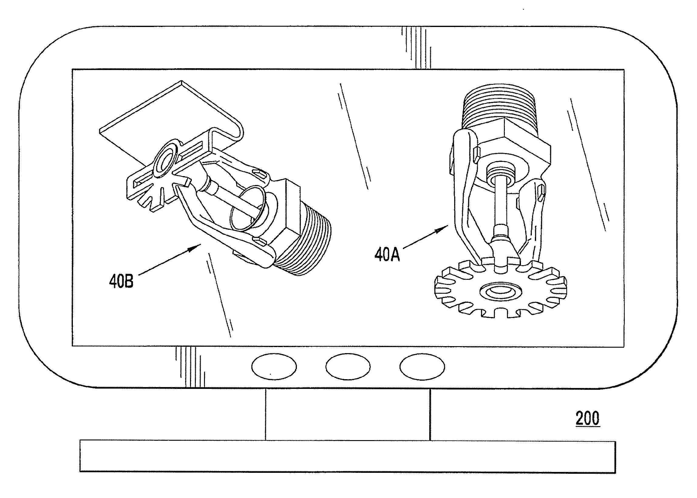
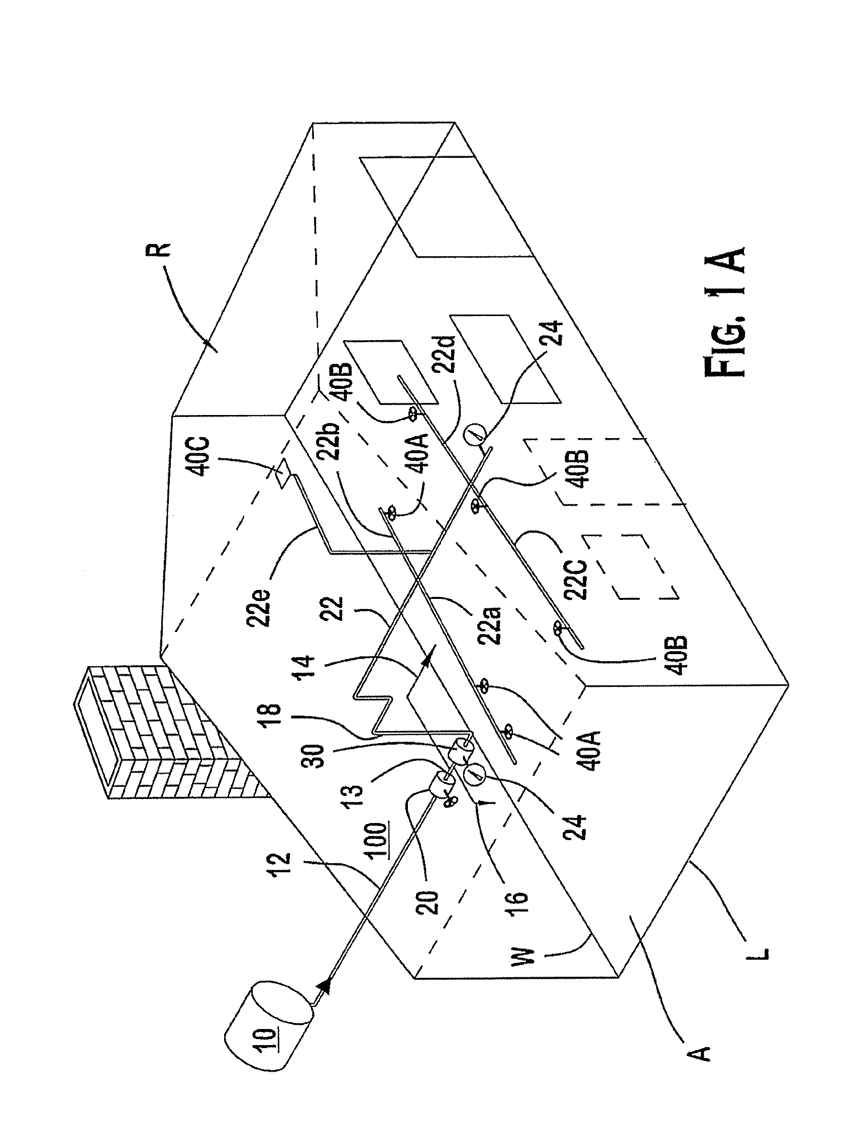
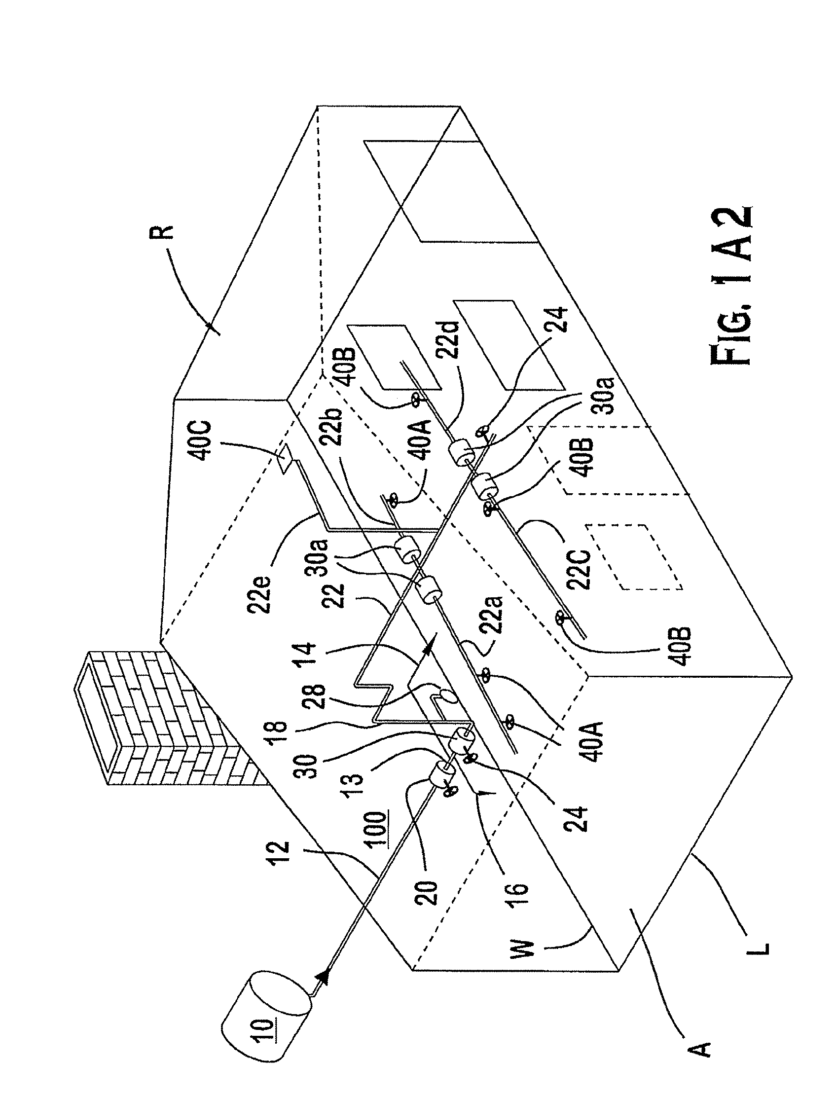
[0131]FIGS. 1-3 illustrate the preferred embodiments. In particular, FIGS. 1A1 and 1A2 show a residential dwelling unit R. As used herein, the term “residential” is a “dwelling unit” as defined in NFPA Standard 13D5 13R (2002), which can include commercial dwelling units (e.g., rental apartments, lodging and rooming houses, board and care facilities, hospitals, motels or hotels) to indicate one or more rooms, arranged for the use of individuals living together, as in a single housekeeping unit, that normally have cooking, living, sanitary, and sleeping facilities. The residential dwelling unit normally includes a plurality of compartments as defined in NFPA Standards 13, 13D, and 13R, where generally each compartment is a space that is enclosed by walls and ceiling. The standards relating to residential fire protection, including 2002 Standards 13, 13D, and 13R, as promulgated by the National Fire Protection Association (“NFPA Standard 13 (2002)”, “NFPA Standard 13D (2002)”, “NFPA S...


PUM


Abstract

Systems and methods for residential fire protection systems in a residential dwelling unit are shown and described. The residential dwelling unit has a plurality of compartments as defined in the 2002 National Fire Protection Association Standards 13, 13D, and 13R. The methods and systems can be achieved by: determining a minimum quantity and location of residential fire sprinklers required to determine a hydraulic demand calculation of the residential fire sprinklers of a piping network filled with water and arranged to protect the plurality of compartments; and specifying the minimum quantity and location of residential fire sprinklers in a piping network filled with a gas. Various aspects of the invention are also shown and described.

Description

CROSS REFERENCE TO RELATED APPLICATIONS[0001]This application is a Continuation-in-part of U.S. patent application Ser. No. 10 / 874,758, filed on Jun. 24, 2004, which is incorporated by reference in its entirety. This application is also a Continuation-in-part of each of U.S. patent application Ser. Nos. 10 / 898,923; 10 / 898,924; 10 / 899,053; 10 / 899,124; 10 / 899,128; 10 / 899,129; and 10 / 899,131, all of which were filed on Jul. 27, 2004, and the contents of which are hereby incorporated by reference in their entirety.BACKGROUND OF THE INVENTION[0002]An automatic sprinkler system is one of the most widely used devices for fire protection. Such a system has sprinklers that are activated once the ambient temperature in an environment, such as a room or a building, exceeds a predetermined value. Once activated, the sprinklers distribute fire-extinguishing fluid, preferably water, in the room or building. A sprinkler system, depending on its specified configuration is considered effective if it...

Claims


Application Information

Patent Timeline
IPC IPC(8): G06F17/50
CPCA62C35/62
Inventor GOLINVEAUX, JAMES E.
Owner TYCO FIRE PRODS LP
Learn More