
Mail delivery system

Inactive Publication Date: 2006-11-28
KÖRBER SUPPLY CHAIN LLC
View PDF61 Cites 7 Cited by
  • Summary
  • Abstract
  • Description
  • Claims
  • Application Information

AI Technical Summary

Benefits of technology

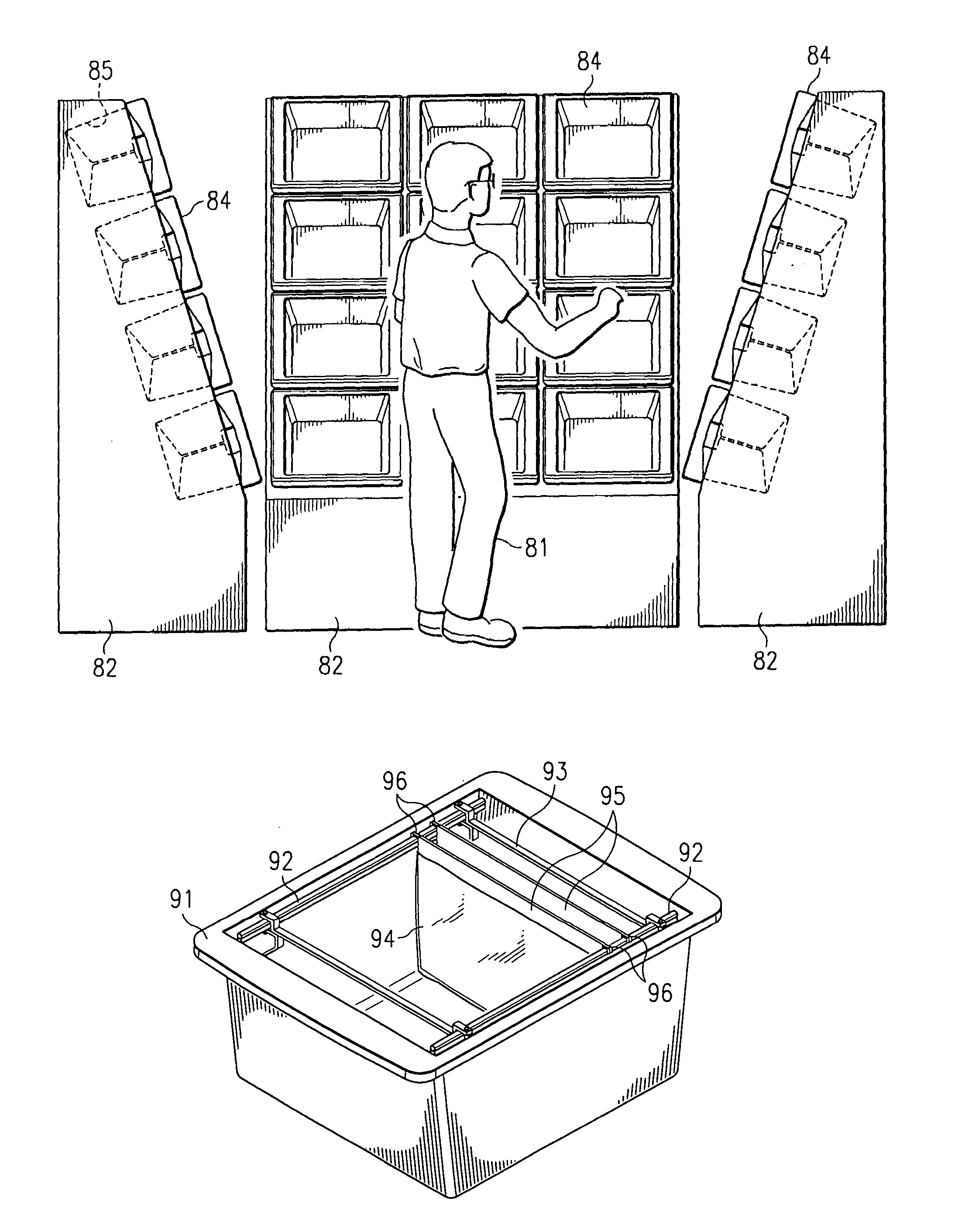
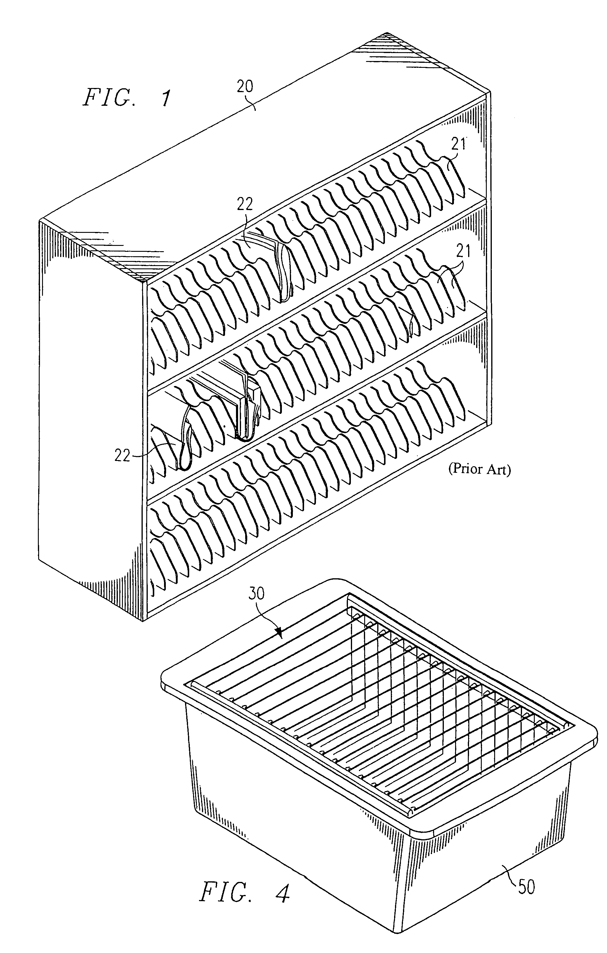
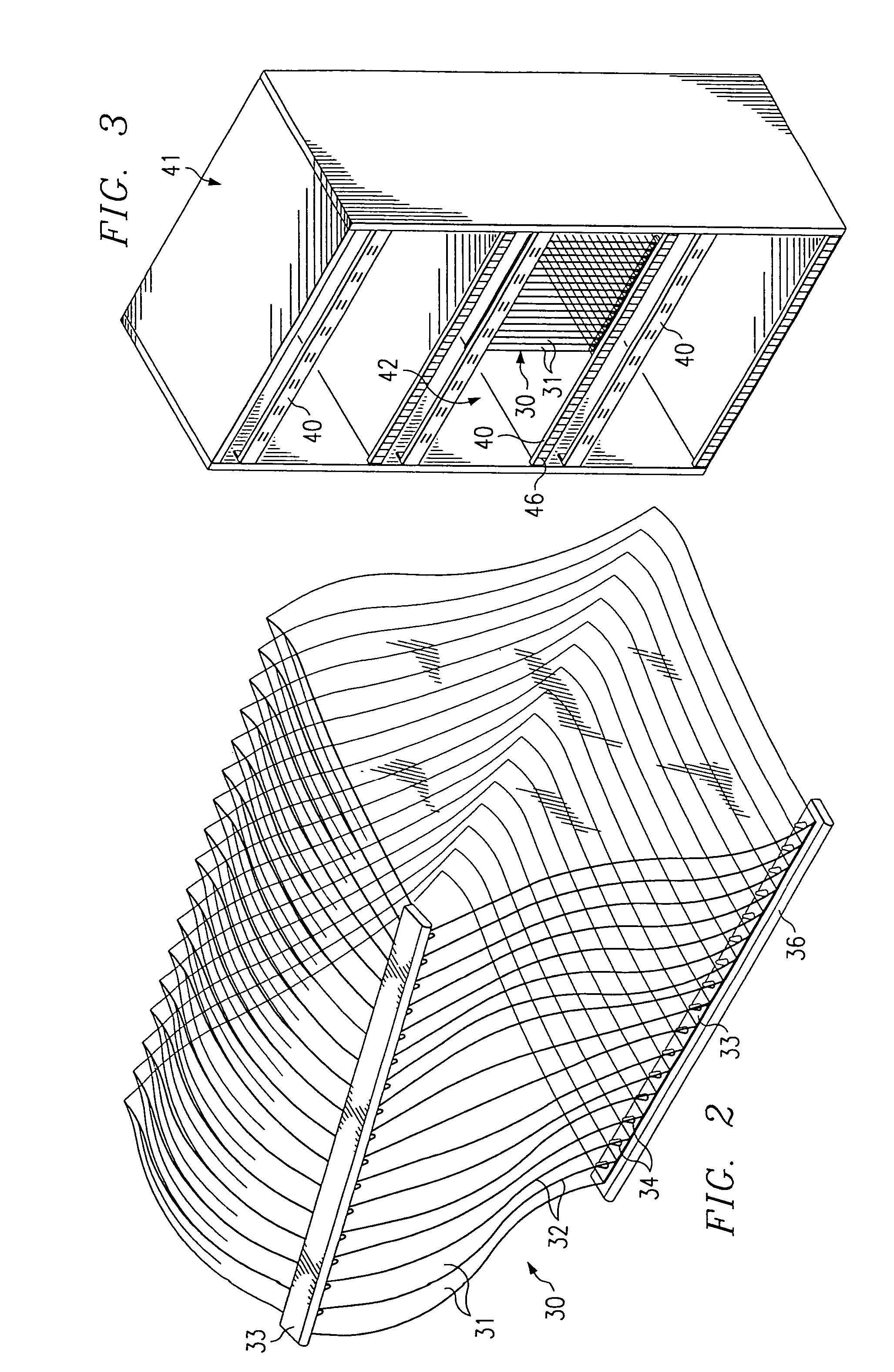
[0010]A newly designed mail case is hereby proposed. It facilitates sequence-sorting various types of mail together into individual bags that each represent unique delivery points. The mail case uses multi-bag inserts so that the bags for several stops can be set up quickly for sorting. At the end of the sorting operation, the entire insert or a portion of it may be pulled down from the case as a single unit to maintain the established delivery point sequence. This eliminates the carrier's need to find separation points or to combine selections from multiple sequenced stacks of mail during the subsequent delivery operation. This results in a dramatic improvement in delivery efficiency. Flexible bag walls allow mail to randomly overfill mail slots that receive greater than the standard volume of mail. This overfilling feature improves efficiency while maintaining slot density.
[0012]A storage device for use in such a method preferably includes a series of flexible, thin-walled bags disposed side by side such that mouths of the bags face a common direction and form a row. The side edges of the mouth of each bag may be integrally bonded (as by fusing or adhesive) to the edges of the mouths of adjoining bags in the widthwise direction of the device to prevent inadvertent insertion of mail between adjacent bags. However, when a case provided with a bag tensioning mechanism is employed, the tension applied to the bags is often sufficient to prevent this, and the bag mouths need not be bonded. The bags are also preferably united by at least one, preferably two reinforcing strips extending in the lengthwise direction of the device. The strips may be formed integrally as part of the multi-bag, or may have suitable means for mounting the series of bags thereon. Preferably a pair of the reinforcing strips are disposed along the top corners of the device on either side of the row of the mouths of the bags. These strips in combination with the means for mounting the bags to the strips should have sufficient strength so that the multi-bag can be manually handled without causing individual bags to separate, yet permit separation of individual bags at the appropriate time, as described hereafter. The strips may also have means thereon for removably securing the storage device to a supporting frame so that the mouths of the bags remain open as items are placed into the bags through the mouths, the strips acting to facilitate loading of the bags into the case.
[0013]The storage device of this invention may optionally provide perforations near the mouth of each bag allowing the bag to be torn off. In such a case, the postal carrier can use the storage device directly as a delivery device, replacing the traditional postal satchel into which loose or rubber-banded bundles of mail are placed. To deliver mail, the carrier carries the device, assisted if needed by handles or a strap provided for that purpose. To deliver mail, the carrier walks or drives his or her route and tears off one bag per delivery address, greatly speeding the delivery process.

Problems solved by technology

However, when a case provided with a bag tensioning mechanism is employed, the tension applied to the bags is often sufficient to prevent this, and the bag mouths need not be bonded.
To deliver mail, the carrier walks or drives his or her route and tears off one bag per delivery address, greatly speeding the delivery process.

Method used


Image

  • Mail delivery system
  • Mail delivery system
  • Mail delivery system

Examples


case 350

[0076]Case 350 operates as follows. When in a first position in which the movable shelf is positioned upwardly from that shown in FIG. 31, the distance between flanges 390, 396 is slightly less than the width of the multi-bags 300. Bottom shelf 364a is supported by a spring loaded stop 380. Stop 380 biases movable frame 354 toward its upper position. Multi-bags 300 may then be manually inserted into case 350 and mounted along opposite sides onto flanges 390, 396 as shown. When the case is fully loaded, the operator then locks the bags 300 into position for sorting by pulling on a handle 384 of a cord 378 or similar device.

[0077]Cord 378 is connected to a series of levers 386, 388 which are in turn connected to the lowermost hinge 374. Pulling on cord 378 causes lever 388 to pull down on hinge 374 and hence on bottom shelf 364a, moving the entire shelf assembly including holder 373 downwardly. A series of links 375 interconnect hinges 374 of each successive shelf 364, preferably at b...


PUM


Abstract

A mail case system facilitates sequence-sorting various types of mail together into individual bags that each represent delivery points. The mail case uses multi-bag inserts so that bags for a number of stops can be set up for sorting. At the end of the sorting operation, the entire insert may be pulled down from the case as a single unit to maintain the established delivery point sequence.

Description

[0001]This application is a divisional of U.S. patent application Ser. No.: 09 / 924,155, filed Nov. 26, 2001, now U.S. Pat. No. 6,715,614.BACKGROUND OF THE INVENTION[0002]Each day more than 200,000 United States Postal Service (USPS) carriers deliver mail to approximately 100 million individual domestic addresses. Mail generally consists of three broad types of items, namely letters, flat mail that is larger than letter mail, and parcels. Before a carrier begins to walk through or drive through his or her delivery route, it is the carrier's responsibility to put all of this mail into an appropriate sequence for efficient delivery.[0003]Under the present USPS procedure, the carrier assembles at least three sequenced stacks of mail, including letters, flats (including enveloped and non-enveloped magazines), and parcels. The carrier may also have one or more additional sequenced stacks, e.g., pre-sorted mass-mail items to be delivered to many or all of the stops on the delivery route. T...

Claims


Application Information

Patent Timeline
IPC IPC(8): B42F17/00B07C3/00B07C7/00B07C7/02
CPCB07C3/00B07C7/00B07C7/02
Inventor PIPPIN, JAMES M.ISAACS, GERALD A.WORTH, II, FLOYD W.
Owner KÖRBER SUPPLY CHAIN LLC
Learn More