Image processing apparatus, image processing method and program

a technology of image processing apparatus and image processing method, applied in the field of image processing apparatus, image processing method and program, can solve the problems of excessive or insufficient density, achieve accurate compensation of image density, eliminate adverse effects caused by change in film status, and improve image density. the effect of compensation

Inactive Publication Date: 2004-11-02
KONICA MINOLTA INC
View PDF5 Cites 7 Cited by
  • Summary
  • Abstract
  • Description
  • Claims
  • Application Information

AI Technical Summary

Benefits of technology

According to this density adjustment method, even if fluctuation in characteristics has occurred to the exposure system and development system subsequent to calibration or even if a difference has occurred to film characteristics, more accurate compensation for image density can be achieved, and the image density of the same diagnostic image signal can be kept within the scope of almost the same density. When a status change has been made to at least one of the aforementioned film, development step, exposure step and density measurement step, a lookup table is re-created, even if there is a sudden change in the characteristics before or after that, and the aforementioned density value for comparison is set again. This feature eliminates the adverse effect caused by change in film status, and ensures more accurate compensation for the image density. The change in film status is defined as a change into the film of a different lot, and refers to the case where film development characteristics undergo sudden changes due to the lot.
For example, the aforementioned development process is carried out by a heating section containing the heating member for heating the film, and a cooling / transporting section for transferring the heated film while cooling it. When the heating member has been replaced and / or cooling / transporting section has been subjected to maintenance, the aforementioned lookup table is created and density value for comparison is set, thereby eliminating the adverse effect due to the fluctuation of the process conditions that have undergone sudden changes caused by replacement of the heating member or replacement of a non-woven fabric such as a guide member coming in contact with the film of the cooling / transporting section.

Problems solved by technology

Accordingly, if an incorrect value is used for this density for comparison, a compensation system will determine that image density is inappropriate even if a process system reproduces an appropriate image (density).
This will result in excessive or insufficient density.

Method used


Image

  • Image processing apparatus, image processing method and program
  • Image processing apparatus, image processing method and program
  • Image processing apparatus, image processing method and program

Examples


first embodiment

(First Embodiment of the Present Invention)

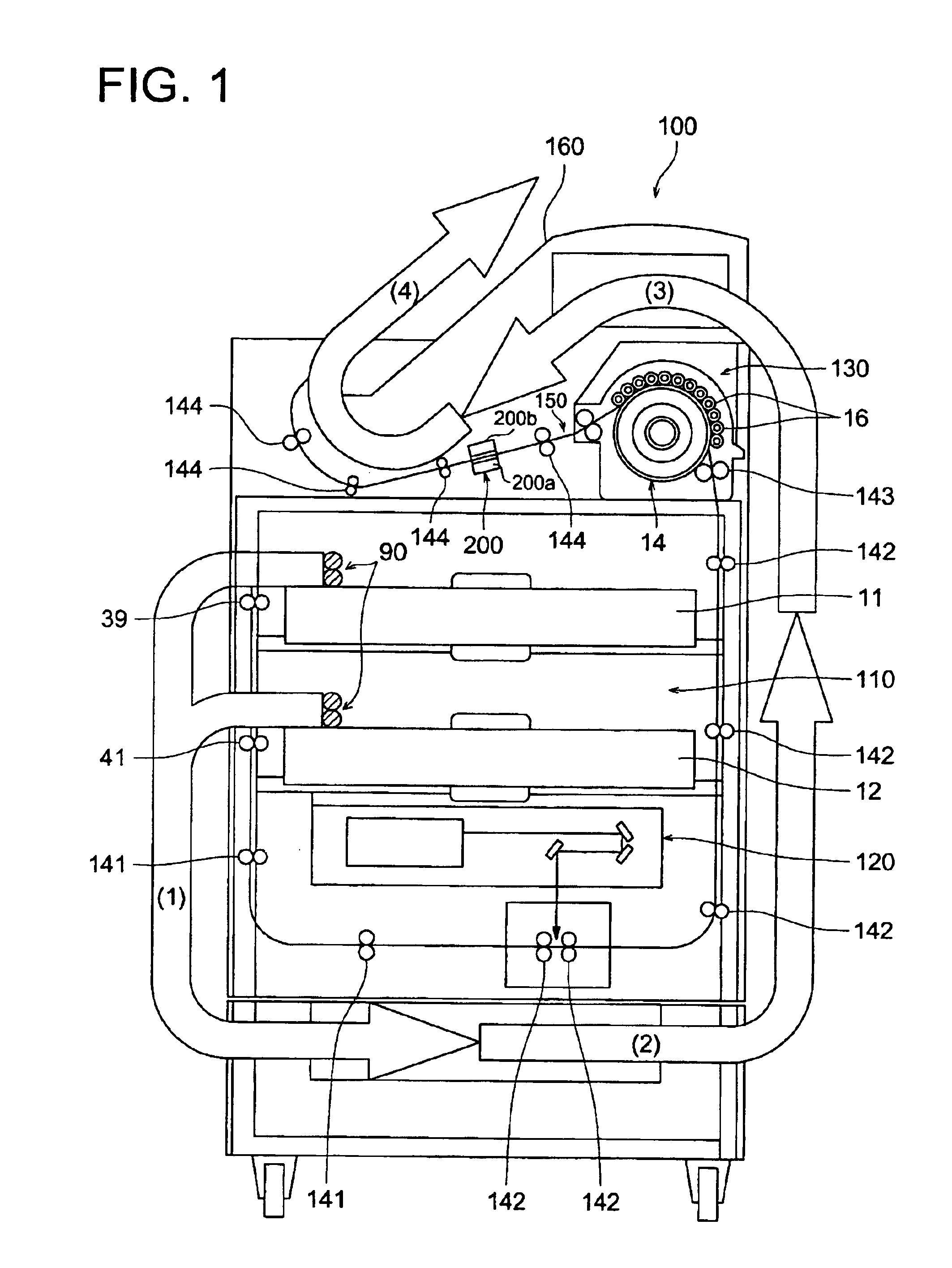
As shown in FIG. 1, an image processing apparatus 100 comprises:

a feed section 110 further including;

a first loading section 11 and a second loading section 12 for loading a package containing a predetermined number of films as sheet-formed heat development photosensitive materials, and

a supply section 90 for transferring and supply each film for exposure and development;

an exposure section 120 for forming a latent image by exposing the film fed from the feed section 110;

a development section 130 for heat development of the film with latent image formed thereon; and

a densitometer 200 for getting information on density by measuring the density of the developed film. Films one by one are fed from the first and second loading sections 11 and 12 by the supply section 90 and transfer roller pairs 39, 40 and 141 in the arrow-marked direction (1) of FIG. 1.

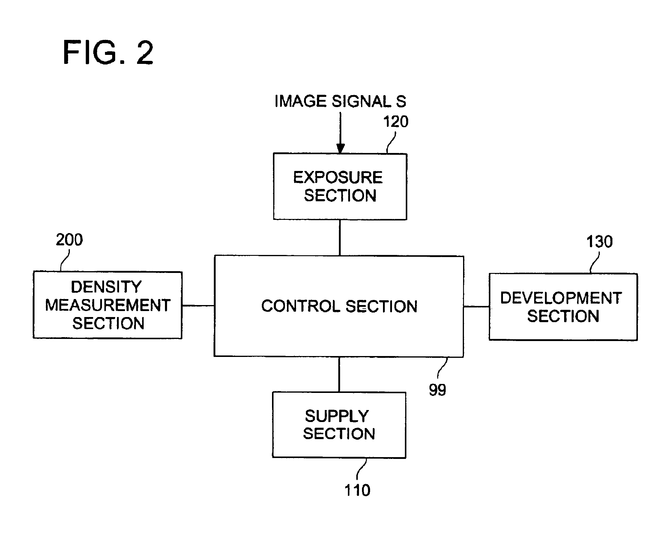
As shown in FIG. 2, the image processing apparatus 100 is provided with a control section 99...

second embodiment

(Second Embodiment of the Present Invention)

The following describes the functions characteristic of the second embodiment of the present invention in the image processing apparatus given in FIG. 1. These functions are realized when controlled by the software program (program) stored in advance in a predetermined storage apparatus such as flash ROM (not illustrated) in the image processing apparatus. The image processing apparatus of the present invention is provided with the microcomputer (computer) containing a CPU (not illustrated). The following functions are performed by running of the program by such a computer.

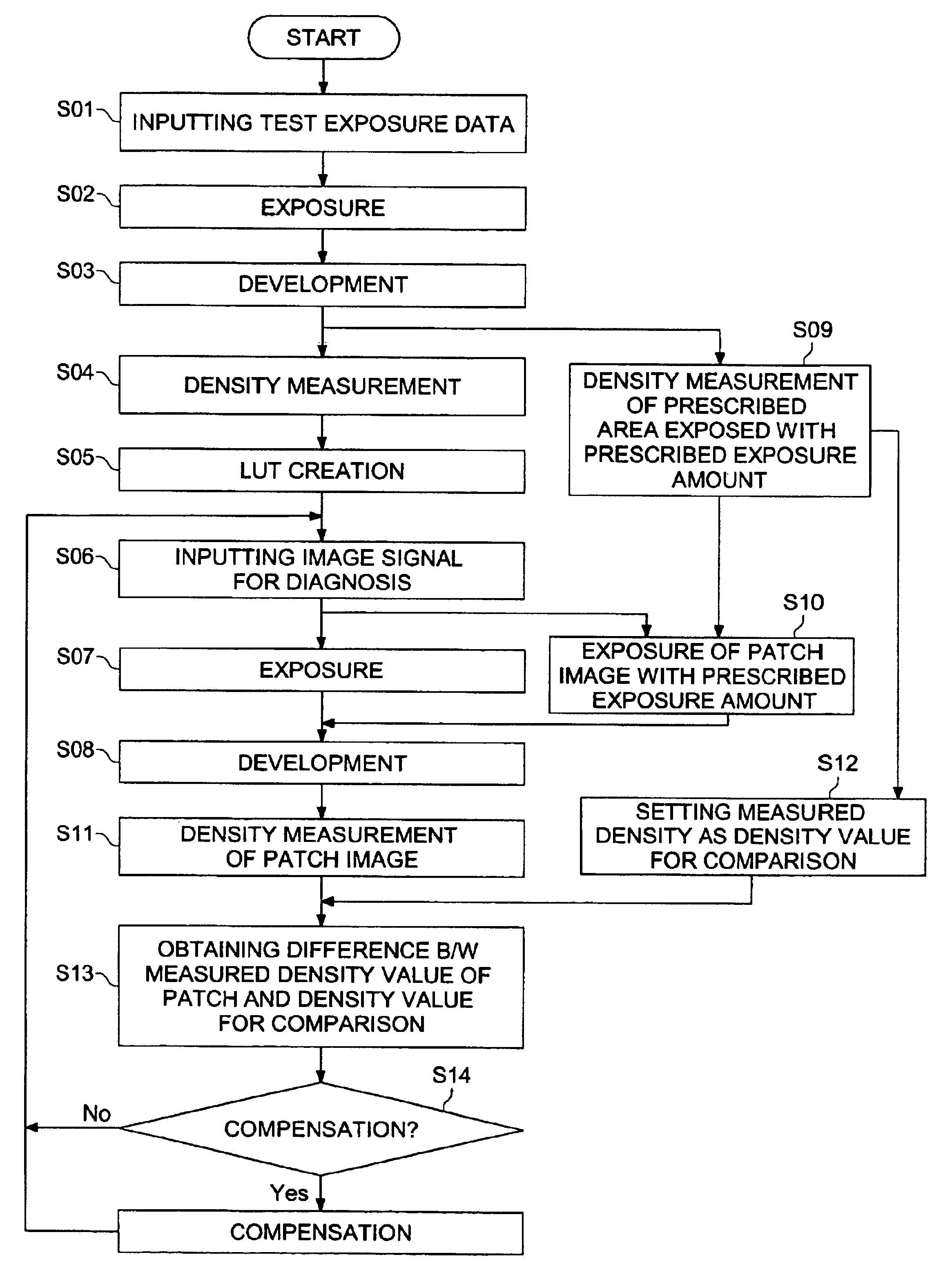
FIG. 11 is a block diagram representing the functions of an image processing apparatus for implementing the image processing method of the present invention. FIG. 12 is a flowchart representing the processing of the image processing apparatus given in FIG. 11.

As shown in FIG. 11, the image processing apparatus of the present invention comprises an exposure section 120 fo...

third embodiment

(Third Embodiment of the Present Invention--3)

The present embodiment includes compensation for density control to be conducted based on the time when power is turned off in the third embodiment--1, and compensation for density control to be conducted based on the temperature when power is turned off in the third embodiment--2.

FIG. 23 is a block diagram representing the functions of the third embodiment of the image processing apparatus for implementing the image processing method of the present invention. FIG. 24 is a flowchart representing the processing of the image processing apparatus given in FIG. 23.

As shown in FIG. 23, the image processing apparatus of the present invention comprises an exposure means 120 for executing the exposure step, a development means 130 for executing the development step, a measuring means 200 for executing the measurement step, a density control means 600 for executing the density control step, a down time monitoring means 700 for executing the down ...


PUM


Abstract

A density adjustment method for adjusting a density of a diagnostic image, having the steps of; exposing an image; developing the latent image; measuring a density of the developed image; creating a lookup table for relating the diagnostic image data and amount of exposure so as to form a density specified by the diagnostic image data; and correcting at least one of an exposure condition and a development condition to ensure that the next film has the optimized density, based on the difference between the measured density of a partial area of the film, and a density for comparison; wherein, a density of a prescribed area in a test exposure image is used as the density for comparison; while the exposure amount is used for exposing the partial area of the film at the time of forming a diagnostic image.

Description

BACKGROUND OF THE INVENTIONThe present invention relates to an image processing apparatus, an image processing method and a program, and particularly to an image processing apparatus, an image processing method and a program that provide appropriate density in a finished film when an image is formed thereon.PRIOR ARTIn the prior art laser imager (image processing apparatus) for medical treatment, a diagnostic image is represented in density gradation. This has created a strong demand for a basic function of outputting always stable density, and various measures have been taken to ensure stable density.The laser imager for medical treatment has a so-called calibration function of controlling the image formation portion to ensure that the digital or video signal sent from each diagnostic apparatus or imaging apparatus has a constant density on a film.Constant density is ensured immediately after calibration has been carried out, but density is subjected to changes for various reasons ...

Claims


Application Information

Patent Timeline
Patent Type & Authority Patents(United States)
IPC IPC(8): H04N1/407G03D13/00H04N1/00H04N1/23
CPCG03D13/002H04N1/4078H04N1/00002H04N1/00015H04N1/00031H04N1/00045H04N1/0005H04N1/00055H04N1/00063H04N1/00087H04N1/0009H04N1/00928H04N1/2307H04N1/2346G03D13/007
Inventor HORIUCHI, MAKOTOUMEKI, MAMORUTAGUCHI, AKIRAONO, YOUICHI
Owner KONICA MINOLTA INC
Why Eureka
Try Eureka