
Table guided by aerostatic bearing elements for vacuum application

a technology of aerostatic bearings and tables, applied in the field of tables, can solve the problems of large installation space and sealing problems, and achieve the effect of satisfying sealing

Active Publication Date: 2009-10-15
VISTEC ELECTRON BEAM
View PDF10 Cites 8 Cited by
  • Summary
  • Abstract
  • Description
  • Claims
  • Application Information

AI Technical Summary

Benefits of technology

[0006]It is the object of the invention to provide a table suitable for use in a vacuum environment which is precision-guided by means of aerostatic bearing elements and in which no constraining forces which could impair the guide characteristics are transmitted during the relative movement between the components of the gas guides, and which ensures a satisfactory seal relative to the vacuum.
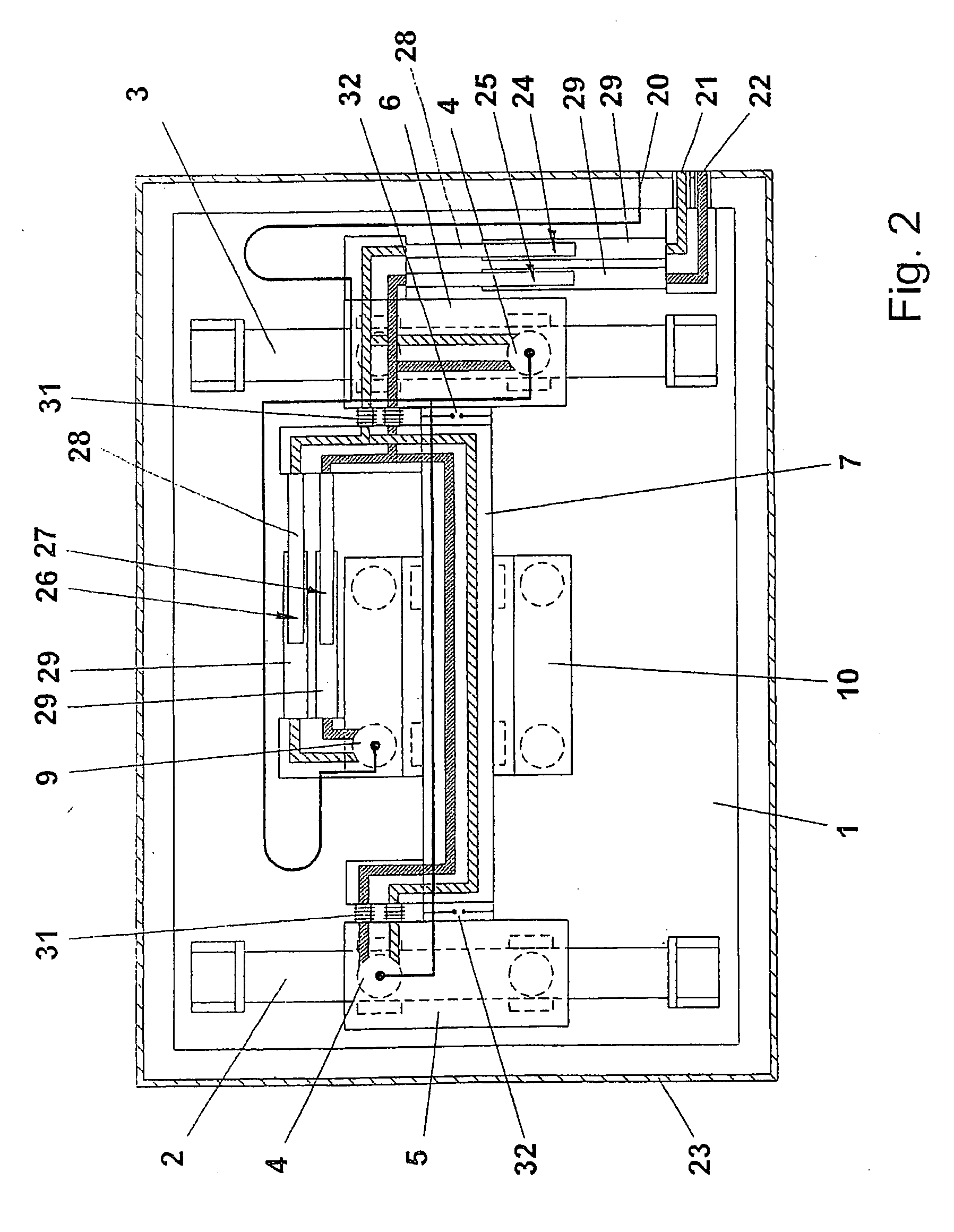
[0011]It is particularly advantageous that the number of variable-length line arrangements provided in the x-direction and y-direction is the same as the number of suction stages arranged one behind the other for gradually reducing the supplied gas flow into the surrounding vacuum, so that a line arrangement with a variable total length is made available for the suction lines of every suction stage of the aerostatic bearing elements.
[0013]In a preferred embodiment example, the respective first pipe member of the line arrangements whose length can be varied in the x-direction is fixedly connected to the fixedly mounted supporting structure which can be constructed as a base plate, and the respective second pipe member, namely, the penetrating pipe, is arranged at a first slide so that the movements of the slide corresponding to the x-axis are not impeded by the penetration of the penetrating pipe(s) into the respective stationary pipe and so that the penetrating pipe is not impeded when moving out because the penetrating pipes also run in the stationary pipe members without contact. In a corresponding manner, the pipe members of the line arrangements whose length is variable in y-direction are arranged at the first slide or connection rail on one side and at the second slide on the other side so that the movement of the slide in y-direction is also not impeded by the noncontacting in-and-out movement of the pipe members.
[0016]In an advantageous embodiment form, an aerostatic bearing element, e.g., an aerostatic bearing bushing, is arranged between the first pipe member and the second pipe member of the variable-length line arrangements for simultaneously guiding and sealing the pipe members. This arrangement is particularly advantageous when a plurality of variable-length line arrangements arranged adjacent to one another are provided for the individual suction stages, and the aerostatic bearing elements of the pipe members are combined to form an assembly. In this way, the gas exiting from these aerostatic bearing elements in direction of the vacuum system can be gradually reduced through single-stage or multi-stage sealing systems of the aerostatic bearing elements, the suction channels of the sealing stages being connected to the corresponding variable-length line arrangements.
[0019]The pipe members are made from a material of high specific rigidity, low coarseness and low adsorption capacity, for example, from high-density ceramics, so that low sealing gap heights can be set in a stable manner in view of the low deflection, the amount of exiting gas is therefore reduced and, when one pipe member moves out of the other. Only a small population of molecules occurs on the surface of the pipe member that is moving out.

Problems solved by technology

This calls for a larger installation space, and sealing problems can occur.

Method used


Image

  • Table guided by aerostatic bearing elements for vacuum application
  • Table guided by aerostatic bearing elements for vacuum application
  • Table guided by aerostatic bearing elements for vacuum application

Examples


Embodiment Construction

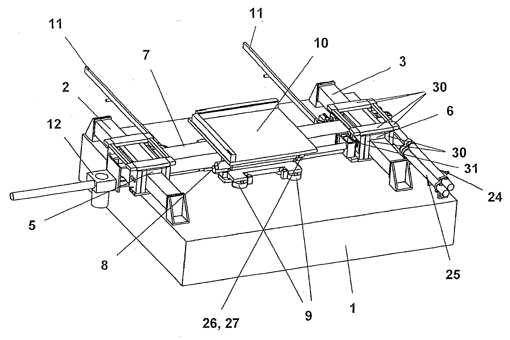
[0028]The table shown in FIG. 1 and FIG. 2 which is precision-guided by aerostatic bearing elements has a fixedly mounted supporting structure which is constructed as a base plate 1. Two guide rails 2, 3 which extend corresponding to an x-axis or in the x-direction and which are constructed as longitudinal bars are fastened to the base plate 1. Movable slides 5, 6 (first slide) run on the guide rails 2, 3 by means of aerostatic bearing elements 4 (see FIG. 2). A connection rail 7 which is constructed as a crossbar is connected to the slides 5, 6 and is displaceable in x-direction together with the slides 5, 6. A slide 8 which is guided on the base plate 1 by aerostatic bearing elements 9 runs along the connection rail 7 forming the y-axis. The bearing elements 4 and 9 can also be constructed only for the base plate or only for the guide rails, respectively. The slide 8 carries a tabletop 10 on which components to be processed, e.g., wafers, are supported. X-drives 11 and a y-drive 1...


PUM


Abstract

The invention is directed to a table for vacuum application which is guided by means of aerostatic bearing elements, having a fixedly mounted supporting structure and a tabletop which is displaceable in x-direction and y-direction with respect to the fixedly mounted supporting structure by means of slides. The slides are provided with the aerostatic bearing elements for guiding, these aerostatic bearing elements being connected to feed lines for supplying the gas required for the operation of the gas bearings and suction lines for removing this gas. The suction lines comprise at least one variable-length line arrangement having a first pipe member and a second pipe member which penetrate one inside the other without contacting, at least one sealing gap being provided between the pipe members.

Description

RELATED APPLICATIONS[0001]This application claims priority to German Patent Application No. DE 10 2008 019 681.9, filed Apr. 11, 2008, which is incorporated herein by reference in its entirety.FIELD OF THE INVENTION[0002]The invention is directed to a table which is precision-guided by gas bearing elements in accordance with the preamble of the main claim and which is suitable for vacuum application.BACKGROUND OF THE INVENTION[0003]Tables of this kind are known in general, for example, from EP 1235115 A2 and U.S. Pat. No. 6,499,880 B2. Gas-guided or air-guided tables of this kind which are suitable for use in a vacuum environment usually comprise two axes which are oriented, for example, in x-direction and y-direction and can move under high-vacuum conditions. Gas bearing elements or air bearing elements are used, for example, on a fixed base plate, for virtually frictionless motion. Usually, slides are movable on guide rails, e.g., in the form of bars, along one axis, e.g., the x-a...

Claims


Application Information

Patent Timeline
Patent Type & Authority Applications(United States)
IPC IPC(8): A47B37/00
CPCB82Y10/00B82Y40/00G03F7/70716G03F7/70816G03F7/70991H01L21/68H01J37/3174H01J2237/182H01J2237/2005H01J2237/20221H01J37/20
Inventor SCHUBERT, GERHARDJACKEL, CHRISTIANKIRSCHSTEIN, ULF-CARSTENBOEHM, MICHAELBAUER, RENEHARNISCH, GERDPESCHEL, THOMASRISSE, STEFANSCHENK, CHRISTOPH
Owner VISTEC ELECTRON BEAM
Learn More