Sealed Vaporization Cartridge and Vaporization Systems for Using

a vaporization system and vaporization cartridge technology, applied in the field of low-cost electronic vaporization systems for inhalation devices, can solve the problems of unvaporized solution, inability to vaporize, contamination problems of existing vaporization systems designed for personal use, etc., and achieve the effect of low cos

Inactive Publication Date: 2009-10-15
NJOY LLC
View PDF7 Cites 109 Cited by
  • Summary
  • Abstract
  • Description
  • Claims
  • Application Information

AI Technical Summary

Benefits of technology

[0008]A base unit includes a power source which connects to the heating element, a switch for activating the power source, and an air port which connects to an airway through the sealed cartridge. In one embodiment, the sealed cartridge plugs into the base unit and is unplugged and disposed of when all the solution has been vaporized. The elements of the sealed cartridge are inexpensive so the cartridge can be replaced with little cost. In another embodiment, the sealed cartridge is fully integrated with the base unit, forming a one-piece unit. The one-piece unit may be disposable, or alternatively may include a refill port which allows a user to refill the sealed cartridge with solution once the contained solution has been fully vaporized.

Problems solved by technology

However, nicotine is typically ingested through cigarettes or chewing tobacco, which have other harmful, even carcinogenic, chemicals in them.
Because it is so poisonous, accidental contact can be fatal.
Some existing vaporization systems store liquid nicotine in media which is prone to leakage.
Further, some of the unvaporized solution may enter the airway that transports the vapor to the user's mouth, which the user may then suck out of the system into his mouth by inhaling.
Existing vaporization systems designed for personal use suffer from contamination problems.
Once a user vaporizes a solution, residue may collect in the system.
If the user then desires a different solution, the vapors of the second solution may be contaminated by chemicals or flavors left over from previous uses.

Method used


Image

  • Sealed Vaporization Cartridge and Vaporization Systems for Using
  • Sealed Vaporization Cartridge and Vaporization Systems for Using
  • Sealed Vaporization Cartridge and Vaporization Systems for Using

Examples


Embodiment Construction

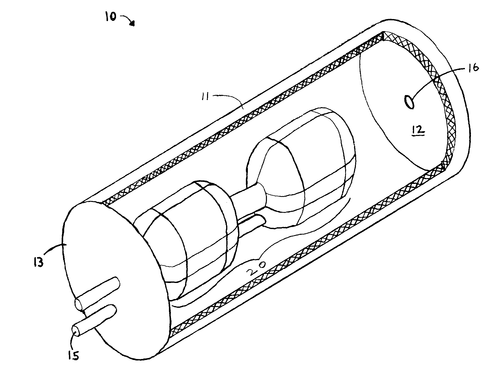
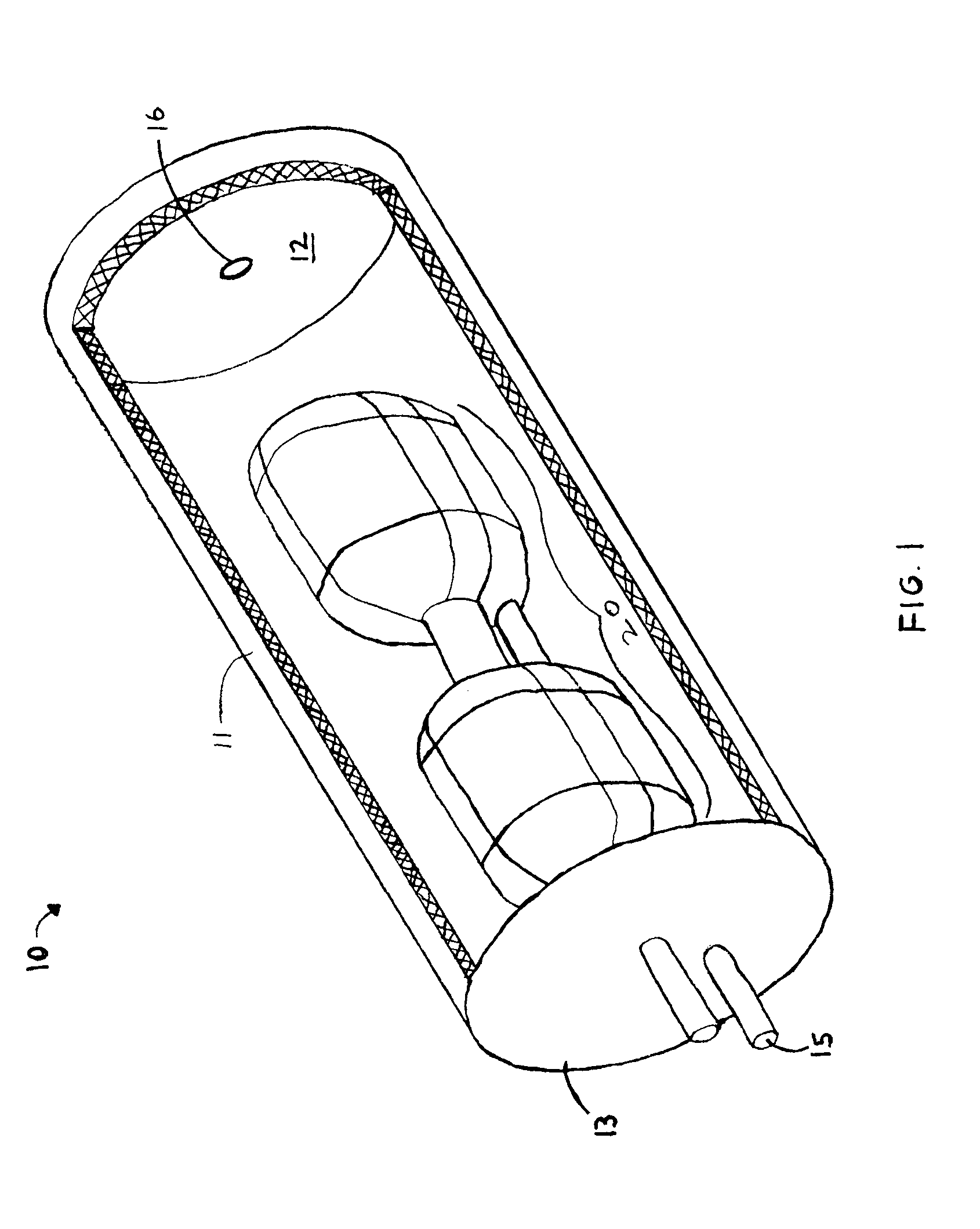
[0024]FIG. 1 illustrates a sealed cartridge, designated generally as 10, for containing a solution to be vaporized. The cartridge 10 is insertable into and removable from a compatible inhalation device, allowing for easy replacement when the solution is exhausted or the functionality of the cartridge 10 begins to degrade. The cartridge 10 is sealed to prevent leakage of the solution inside until the cartridge 10 is to be used, allowing for safe handling of the cartridge 10 by a user. A compatible inhalation device, such as those described below and illustrated in the figures, has a power source with terminals that align with the cartridge 10 when it is inserted into the inhalation device, creating an electrical contact that allows the user to activate the device and vaporize the solution in the cartridge 10.

[0025]The cartridge 10 has a shell 11 with a base 12 and a cap 13 attached to the shell 11 to create a hollow space therein. The hollow space contains a vaporizing system 20 for ...


PUM


Abstract

A vaporization system for an inhalable substance includes a sealed cartridge. The sealed cartridge contains the chemical solution to be vaporized, a heating element which vaporizes the solution, and a wicking material for retaining the solution and bringing it into contact with the heating element through capillary action. The sealed cartridge may be disposable, having inexpensive elements so the cartridge can be replaced with little cost. Alternatively the sealed cartridge may be fully integrated with other components into a base unit, which may be disposable or may include a refill port which allows a user to refill the sealed cartridge with solution once the contained solution has been fully vaporized. A power source connects to the heating element and is activated by a switch that may be a breath detector. A disposable mouthpiece may be connected to the cartridge. The mouthpiece has an airway through which the vaporized solution is inhaled. The airway is restricted by a trap that prevents unvaporized droplets of the solution from passing through the airway into a user's mouth.

Description

CROSS-REFERENCE TO RELATED APPLICATIONS[0001]This application claims the benefit of co-pending provisional application No. 61 / 124,114 filed Apr. 11, 2008.FIELD OF INVENTION[0002]This invention relates to inhalation devices. This invention relates particularly to a low-cost electronic vaporization system for an inhalation device that prevents leakage of the substance to be vaporized.BACKGROUND[0003]The delivery of chemicals, particularly medicaments and other compounds having a physical or physiological effect on a person, can be accomplished by vaporizing a solution containing the desired elements; the vapor is then inhaled by the user, whereby the desired elements enter the user's blood stream through the lungs. The solution is typically vaporized by bringing it into contact with a heating element. Where the chemical compound is contained in a plant, this delivery method is often preferred to burning the plant because it eliminates the ingestion of smoke and other combustion byprod...

Claims


Application Information

Patent Timeline
Patent Type & Authority Applications(United States)
IPC IPC(8): A61M16/12
CPCA61M15/0028A61M11/041
Inventor PATERNO, GREG
Owner NJOY LLC
Why Eureka
Try Eureka