
Method of producing pneumatic tire

Inactive Publication Date: 2009-10-15
YOKOHAMA RUBBER CO LTD
View PDF3 Cites 1 Cited by
  • Summary
  • Abstract
  • Description
  • Claims
  • Application Information

AI Technical Summary

Benefits of technology

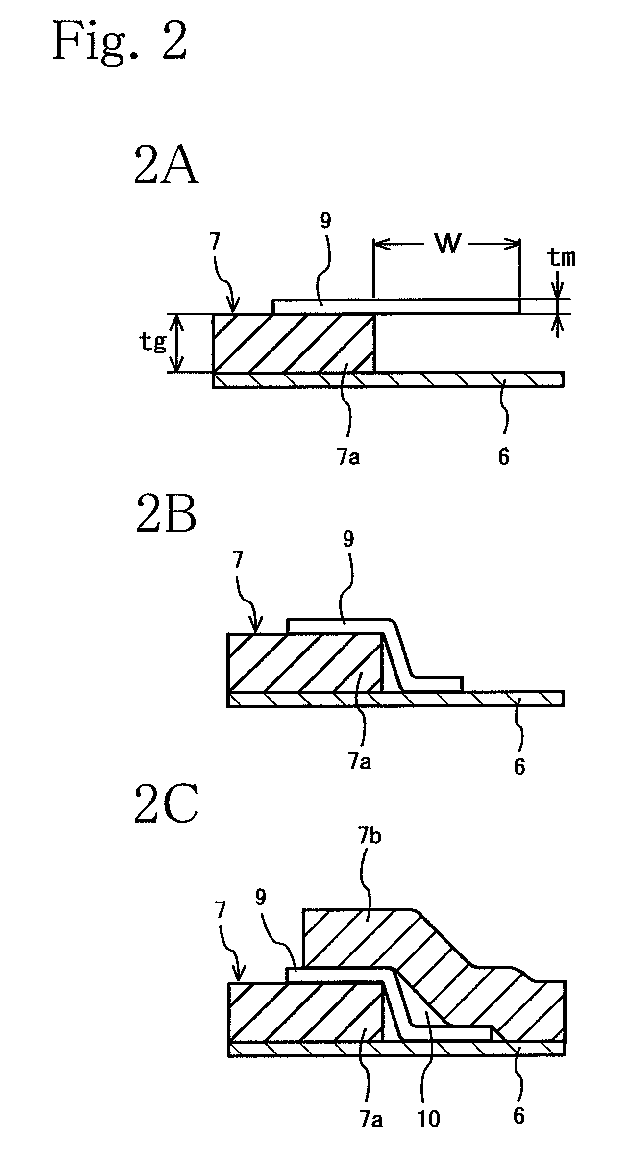
[0008]The method of producing a pneumatic tire according to the present invention provides the following effects. In the method, when the tie-rubber sheet is wound on the thermoplastic resin film and both end portions of the tie-rubber sheet are overlapped and spliced with each other in a step-like shape, the unvulcanized auxiliary rubber sheet is bonded onto the winding start portion of the tie-rubber sheet so as to project in the circumferential direction, and then the winding end portion of the tie-rubber sheet is overlapped thereon. Accordingly, the amount of air to be trapped in the spliced portion is reduced by the auxiliary rubber sheet being provided, and the amount of air to be absorbed during a curing process is increased. As a result, occurrence of blisters can be prevented.

Problems solved by technology

However, although there is an increasing demand for a reduction in weight of pneumatic tires, it has been difficult to achieve the reduction in weight when using the butyl rubber because the butyl rubber has a large specific gravity.
However, the thermoplastic resin film has no such air absorbability as the butyl rubber has.
For this reason, a problem arises in that, if air is trapped in an uncured tire in the forming of the uncured tire, the trapped air leads to occurrence of blisters in an inner surface of the thermoplastic resin film after a curing process.
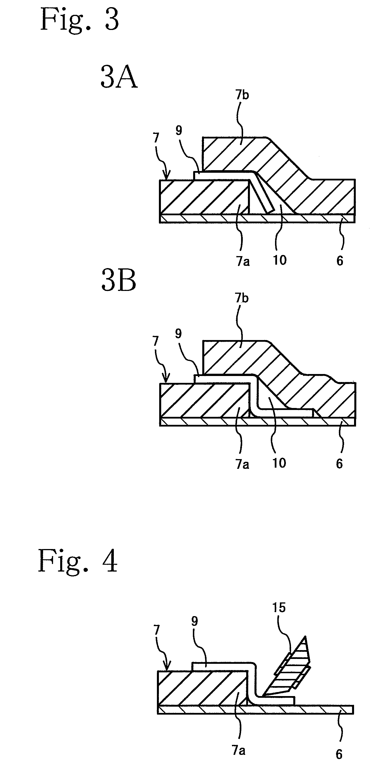
If the green tire thus formed is cured, the air in the void 10 is not fully absorbed into the rubber layer, thus leading to occurrence of blisters.
Such blisters not only significantly disfigure the inner surface of the tire, but also may cause a breakage or separation of the thermoplastic resin film during use of the tire.
In this case, because a tie-rubber sheet needs to be formed with a large thickness in order to prevent the biting, such tires have a problem in that the aforementioned failure is more likely to occur.

Method used


Image

  • Method of producing pneumatic tire
  • Method of producing pneumatic tire
  • Method of producing pneumatic tire

Examples


examples 1 to 3

and Conventional Example

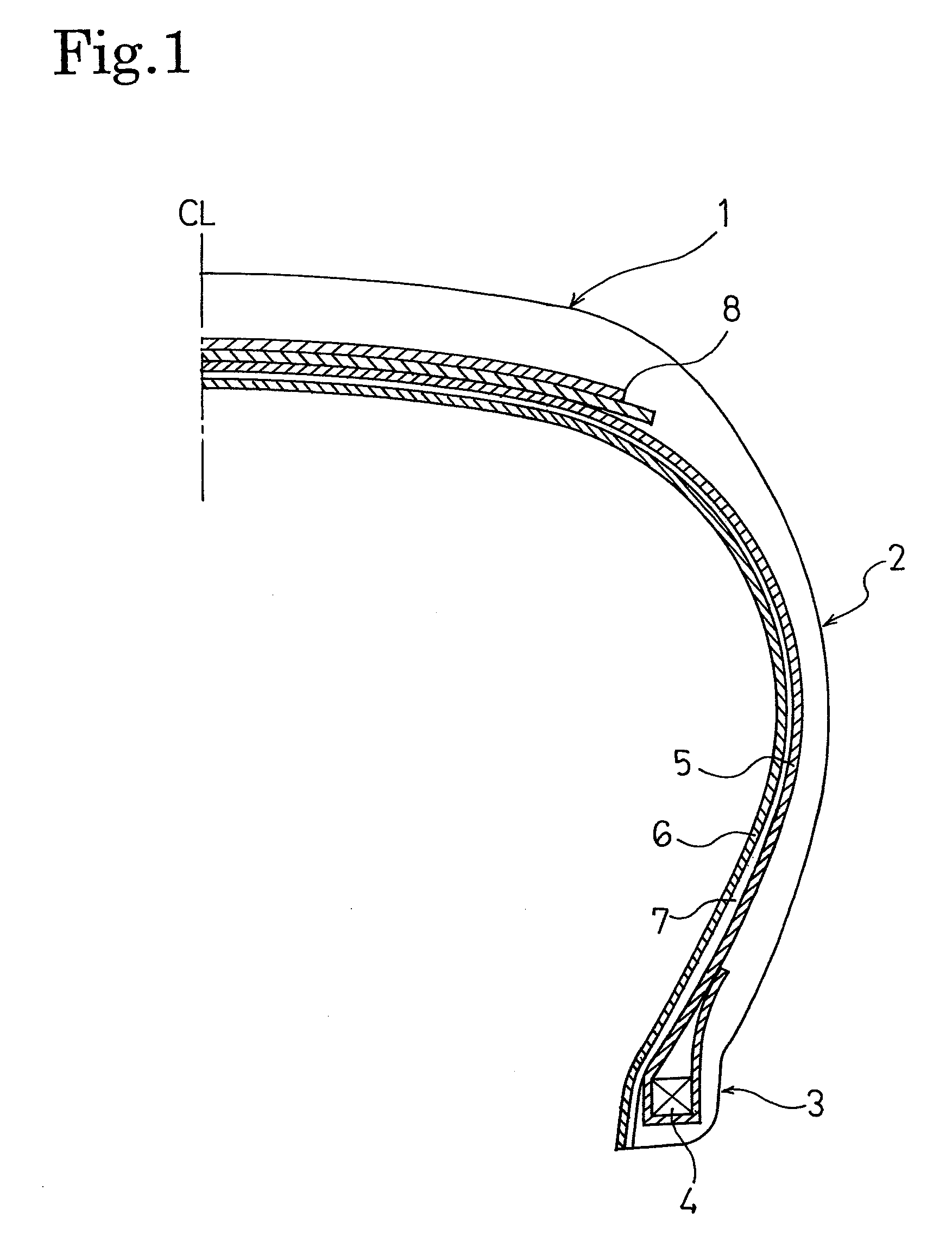
[0030]Four types of green tires (Examples 1 to 3 and Conventional Example) each having a tire size of 195 / 65R15 and a tire structure shown in FIG. 1 were formed. In each of the green tires, a cylindrical thermoplastic resin film (having a 0.2 mm thickness) was used as an air permeation prevention layer, and a tie-rubber sheet having a 0.7 mm thickness and a carcass layer were overlapped and spliced with the air permeation prevention layer. In addition, these green tires were formed to be different from one another, when the above described tie-rubber sheet was wound, as shown in Table 1, in whether or not an auxiliary rubber sheet was used, the length (W) of projection, and whether or not stitching was performed. Each of these four types of green tires was inserted into a curing mold and cured therein, and then was evaluated in terms of the size of void of trapped air in the green tire thus formed, whether or not blisters had occurred after the curing process...


PUM

PropertyMeasurementUnit
Thicknessaaaaaaaaaa
Thicknessaaaaaaaaaa
Thicknessaaaaaaaaaa

Abstract

Provided is a method of producing a pneumatic tire where occurrence of blisters caused by trapped air is prevented even if a thermoplastic resin film is used as an air permeation prevention layer. The method includes: wrapping a thermoplastic resin film (6) around a making drum (20); winding an unvulcanized tie-rubber sheet (7) on the thermoplastic resin film (6) in a manner that a winding start portion (7a) and a winding end portion (7b) of the tie-rubber sheet (7) are overlapped with each other; and thereafter winding a carcass layer (5) on the tie-rubber sheet (7). In the method, an unvulcanized auxiliary rubber sheet (9) is bonded onto the winding start portion (7a) of the tie-rubber sheet (7) so as to project in a circumferential direction, and then the tie-rubber sheet (7) is wound in a manner that the winding end portion (7b) of the tie-rubber sheet (7) is stacked on the auxiliary rubber sheet (9).

Description

TECHNICAL FIELD[0001]The present invention relates to a method of producing a pneumatic tire. More specifically, the present invention relates to a method of producing a pneumatic tire where, even if a thermoplastic resin film is used as an air permeation prevention layer, occurrence of blisters in an inner surface of the thermoplastic resin film is prevented.BACKGROUND ART[0002]In a tubeless pneumatic tire, the inner surface of the tire is lined integrally with an air permeation prevention layer (an inner liner), and a butyl rubber excellent in air non-permeability is used as a material for the air permeation prevention layer. However, although there is an increasing demand for a reduction in weight of pneumatic tires, it has been difficult to achieve the reduction in weight when using the butyl rubber because the butyl rubber has a large specific gravity. In this respect, Patent Document 1 proposes the use of a thermoplastic resin film having a small specific gravity as an air per...

Claims


Application Information

Patent Timeline
IPC IPC(8): B29D30/20
CPCB29D30/0681B29D30/20B29L2030/008B29D2030/0682B29K2101/12B29D30/30
Inventor SAWADA, TAKAHIKO
Owner YOKOHAMA RUBBER CO LTD
Learn More