Electric power collection/distribution ring of rotary electric machine

a technology of electric power collection and distribution rings, which is applied in the direction of dynamo-electric machines, electrical apparatus, windings, etc., can solve the problems of reducing the degree of freedom in spatial design of motors, further increasing the size of motors, and difficulty in increasing the number of pole pairs, so as to prevent disturbances from being generated in wire windings

Active Publication Date: 2009-10-15
HONDA MOTOR CO LTD
View PDF9 Cites 79 Cited by
  • Summary
  • Abstract
  • Description
  • Claims
  • Application Information

AI Technical Summary

Benefits of technology

[0010]According to the above first aspect of the present invention, since the connection terminals that can be connected to one of the leader line sections of the coils is fixed in a predetermined position, it is possible to easily connect each coil to one of the bus ring via the connection terminal only in a single operation of connecting between the leader line section of each coil and one of the connection terminal by means of fusing (thermal caulking) or the like. Moreover, it is possible to prevent an excessive increase in the working area required for this connecting operation, while preventing a reduction in the degree of freedom in the spatial designing for the rotary electric machine. Furthermore, it is possible to reduce the number of components and the cost required for the configuration thereof, while simplifying the manufacturing steps.
[0027]According to the above ninth aspect of the present invention, when leading out the leader line section radially outward from the coils, it is possible to appropriately perform a bending process. For example, even in the case where edgewise bending is required in a rectangular wire, it is possible to prevent a disturbance being generated in wire winding.

Problems solved by technology

Therefore, in such a motor, it is difficult to increase the number of pole pairs without increasing the radial direction dimension of the motor for example.
As a result, there is a problem of a reduced degree of freedom in the spatial designing for the motor.
As a result, there is a problem of a further increase in the size of the motor.
Moreover, in the electric power collection / distribution member of the motor according to the above second conventional technique, a plurality (three types) of different clips are used for holding the three phase bus bars to each other, and consequently the number of components and the cost required for the configuration thereof increases.
As a result, there is a problem in that the manufacturing steps of the electric power collection / distribution member become cumbersome.

Method used


Image

  • Electric power collection/distribution ring of rotary electric machine
  • Electric power collection/distribution ring of rotary electric machine
  • Electric power collection/distribution ring of rotary electric machine

Examples


first embodiment

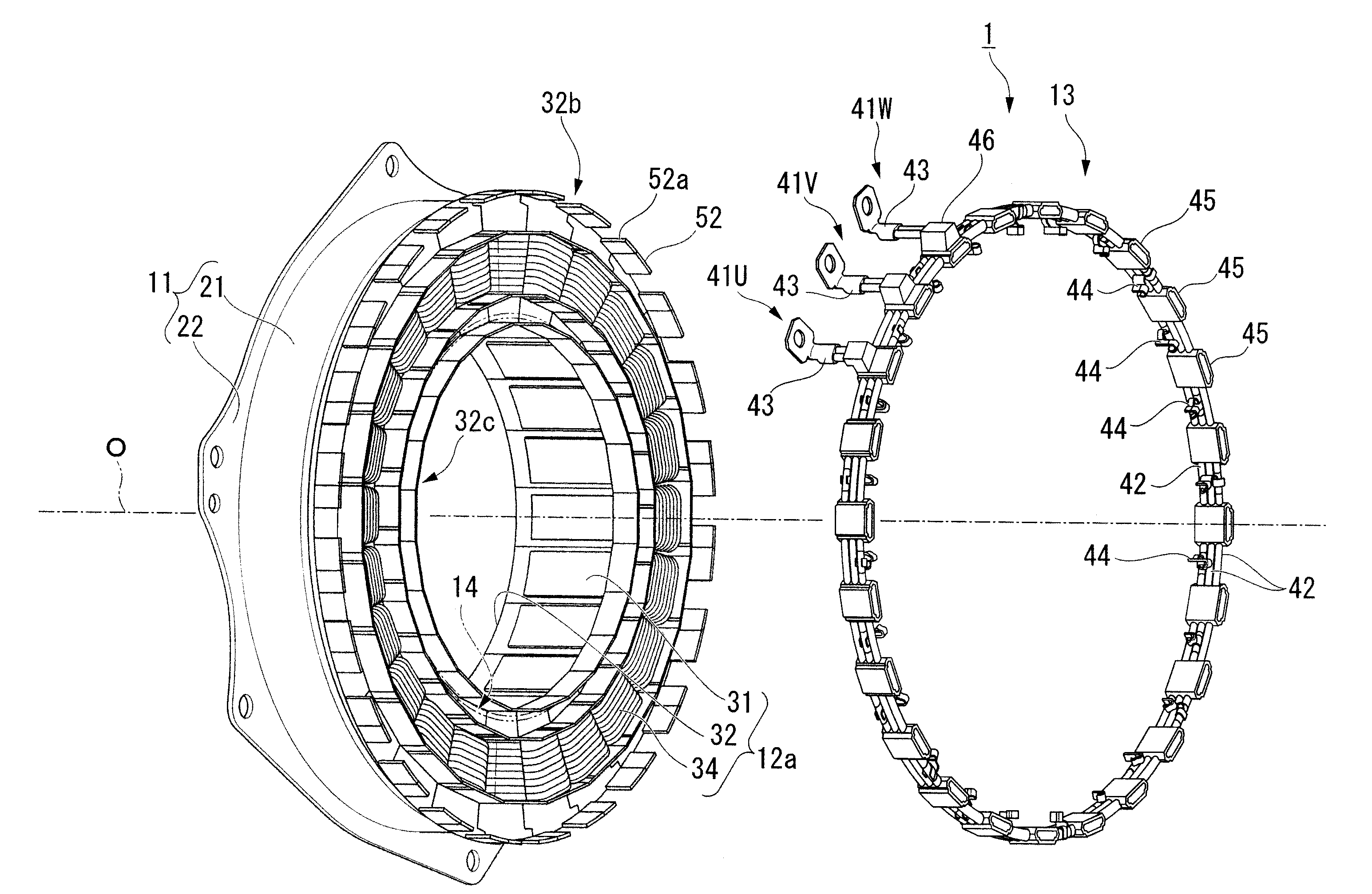
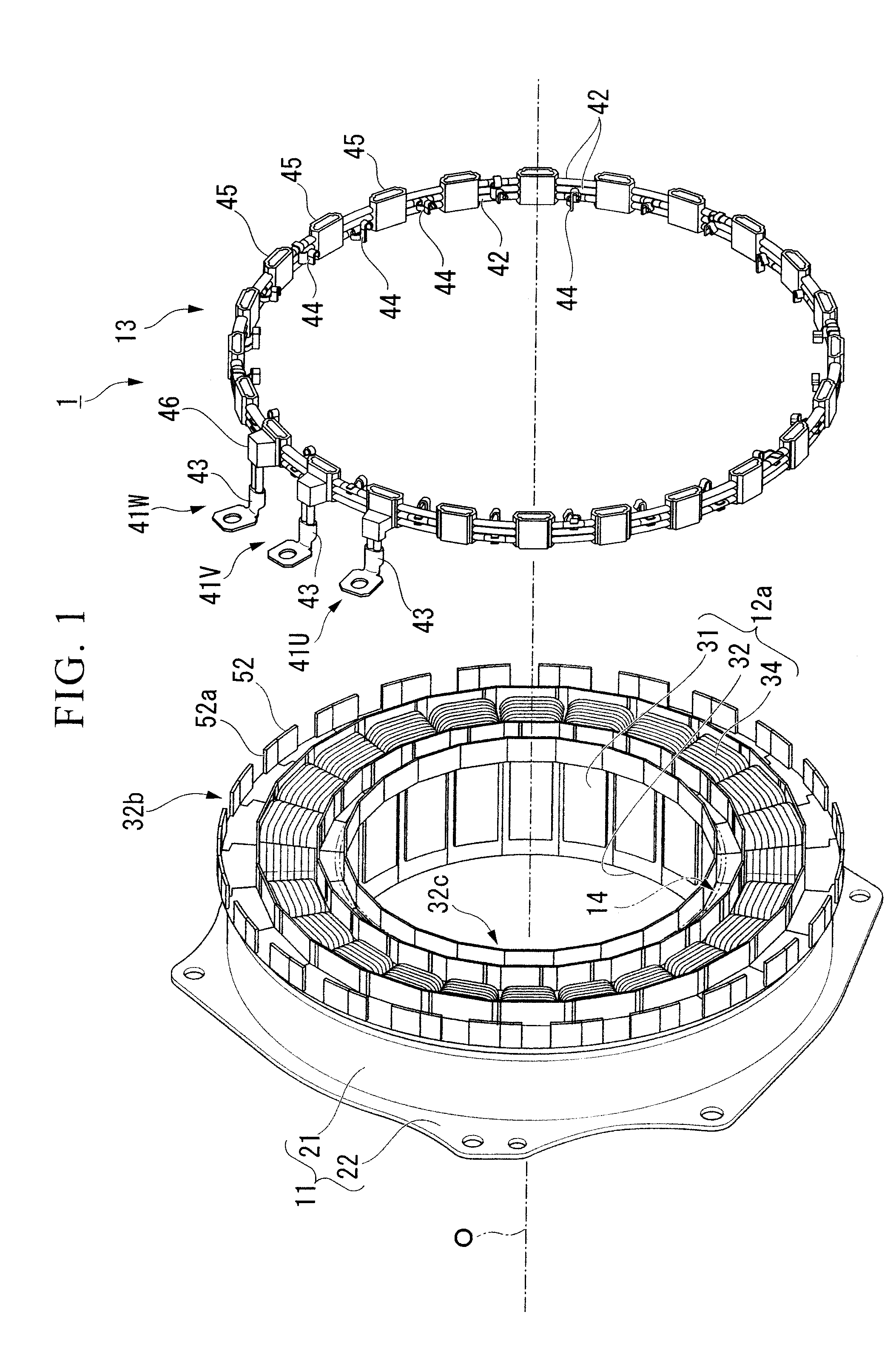
[0050]Hereunder, an electric power collection / distribution ring (connection structure for electric power collection / distribution) of a rotary electric machine according to a first embodiment of the present invention is described, with reference to the drawings.

[0051]The electric power collection / distribution ring of a rotary electric machine according to the present embodiment (for example, an electric power collection / distribution member 13 described later) may be used for a stator 1 of a rotary electric machine to be installed, for example, as a travelling drive source in a vehicle such as a hybrid vehicle or an electric vehicle.

[0052]The stator 1, for example, is an inner rotor type stator in which a rotor (not shown in the drawing) is to be arranged on the inner circumferential side thereof as shown in FIG. 1.

[0053]The stator 1 is provided, for example, with a stator holder 11, a ring shaped stator set 12 including a plurality of stator pieces 12a arranged in a ring shape, a rin...

second embodiment

[0092]Hereunder, an electric power collection / distribution ring (connection structure for electric power collection / distribution) of a rotary electric machine according to a second embodiment of the present invention is described, with reference to the accompanying drawings.

[0093]The electric power collection / distribution ring of a rotary electric machine according to the present embodiment (for example, a ring shaped stator set 112 and an electric power collection / distribution member 113 described later) may be used for a stator 101 of a rotary electric machine to be installed, for example, as a travelling drive source in a vehicle such as a hybrid vehicle or an electric vehicle.

[0094]The stator 101, for example, is an inner rotor type stator in which a rotor (not shown in the drawing) is to be arranged on the inner circumferential side thereof as shown in FIG. 12.

[0095]The stator 101 is provided, for example, with a stator holder 111, a ring shaped stator set 112 including a plura...


PUM


Abstract

An electric power collection / distribution ring of a rotary electric machine including: a plurality of ring shaped bus rings each of which is to be connected to one of a plurality of coils provided in the rotary electric machine, the coils each corresponding to phases of the rotary electric machine; a plurality of fixing member which are fixed to the bus rings and arranged along the circumferential direction thereof; and a plurality of connection terminals which are fixed to the bus rings and arranged along said circumferential direction, and which can be connected with one of leader line sections of the coils.

Description

BACKGROUND OF THE INVENTION[0001]Priority is claimed on Japanese Patent Application No. 2008-105539, filed Apr. 15, 2008, and Japanese Patent Application No. 2008-105540, filed Apr. 15, 2008, the contents of which are incorporated herein by reference.FIELD OF THE INVENTION[0002]The present invention relates to an electric power collection / distribution ring (connection structure for electric power collection / distribution) of a rotary electric machine.DESCRIPTION OF THE RELATED ART[0003]Heretofore, for example, there has been known a motor in which a plurality of concentrated winding stator coils is connected by means of fusing (thermal caulking) into a ring shaped bus ring. In this motor, the connection between the plurality of concentrated winding stator coils and the ring shape bus ring is achieved by: arranging wire connection members so as to be adjacent to U-shape curved terminal sections in the circumferential direction, the terminal sections protruding from the bus ring in the...

Claims


Application Information

Patent Timeline
Patent Type & Authority Applications(United States)
IPC IPC(8): H02K3/52
CPCH02K3/522H02K2203/12H02K2203/09
Inventor INOUE, MASASHISATO, HIROYUKINAKAJIMA, MINORU
Owner HONDA MOTOR CO LTD
Why Eureka
Try Eureka