Load Control Device Having a Visual Indication of an Energy Savings Mode

a technology of energy saving mode and control device, which is applied in the direction of discharge tube/lamp details, electric discharge lamps, discharge tube incandescent screens, etc., can solve the problem of not having a visual indication that the high-end trim has been adjusted, and achieve the effect of reducing the amount of power

Inactive Publication Date: 2009-10-15
LUTRON TECH CO LLC
View PDF31 Cites 135 Cited by
  • Summary
  • Abstract
  • Description
  • Claims
  • Application Information

AI Technical Summary

Benefits of technology

[0011]According to yet another embodiment of the present invention, a wallbox dimmer switch is adapted to be coupled between a power source and an electrical load for controlling the amount of power delivered to the electrical load between a maximum value and a minimum value. The wallbox dimmer switch comprises a dimmer circuit for controlling the power applied to the load between the full power value and the reduced value, a first manually-operable control structure for controlling the dimmer circuit, a second manually

Problems solved by technology

Prior art dimmer switches typically have fixed high-end trims and provide no user-accessible means for a user to be

Method used


Image

  • Load Control Device Having a Visual Indication of an Energy Savings Mode
  • Load Control Device Having a Visual Indication of an Energy Savings Mode
  • Load Control Device Having a Visual Indication of an Energy Savings Mode

Examples


first embodiment

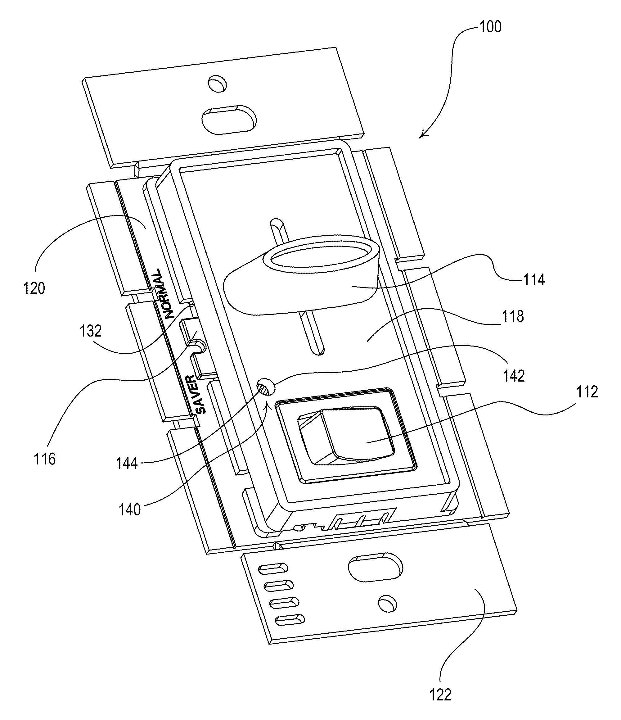
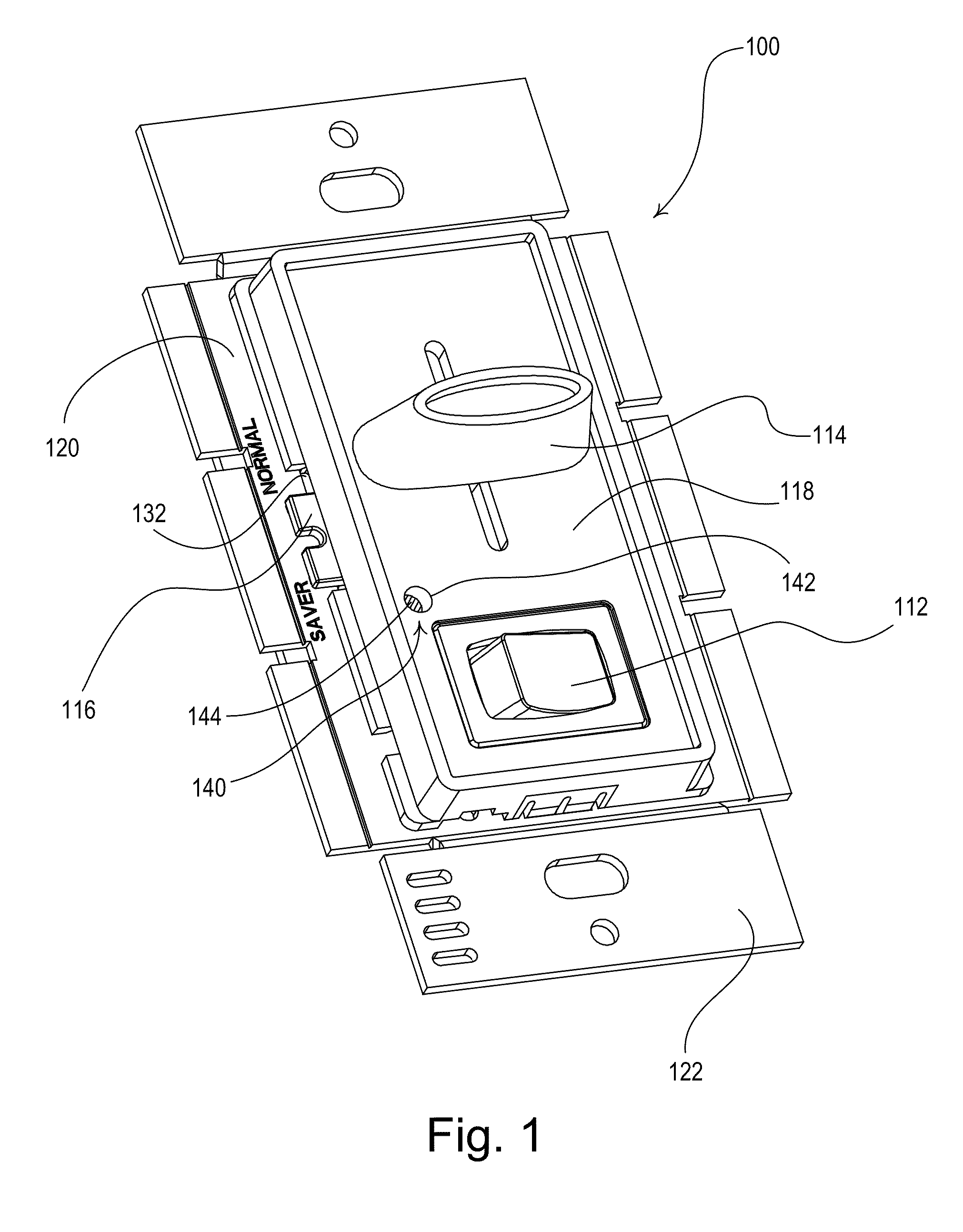
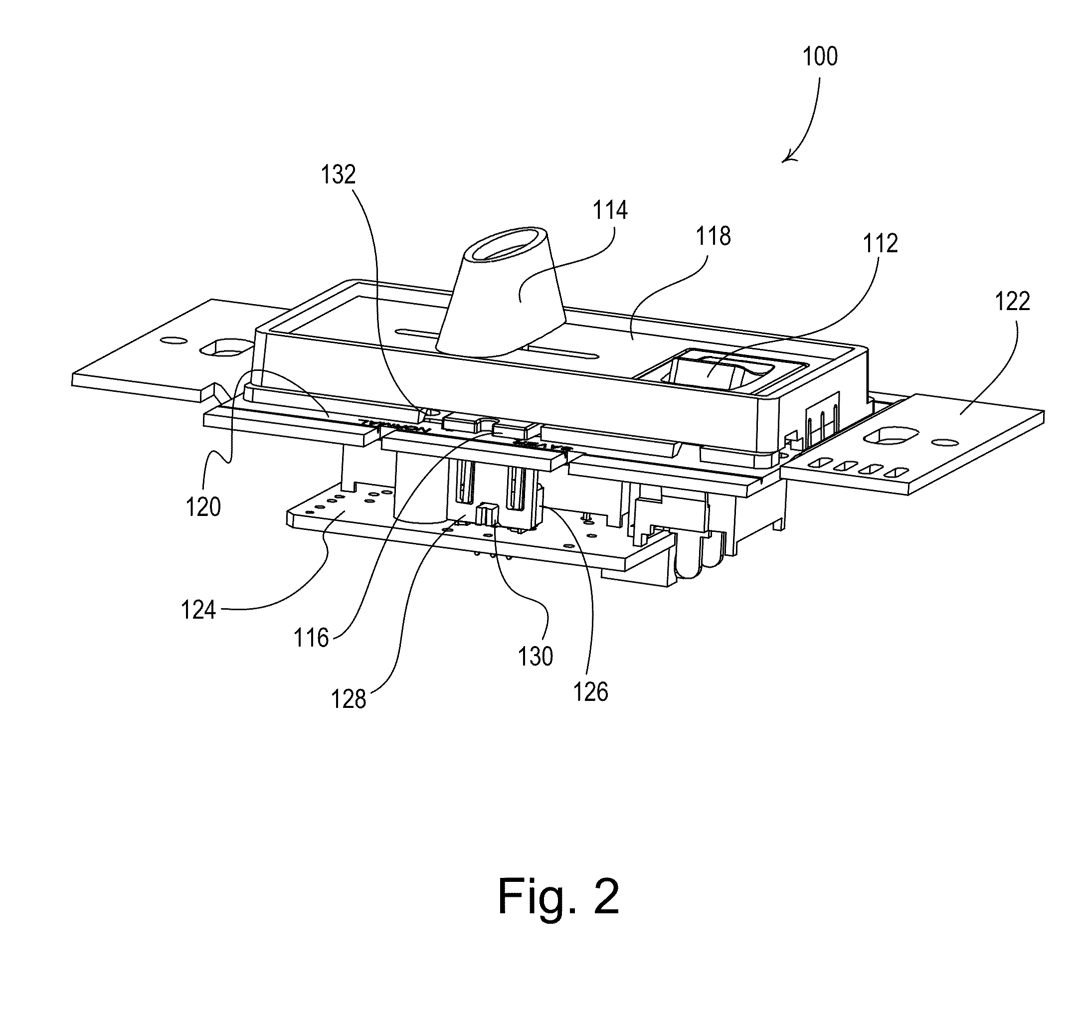
[0032]FIGS. 1 and 2 are perspective views of the user interface of a wallbox dimmer switch 100 that provides an energy-saver (ES) mode according to the present invention. The dimmer switch 100 is adapted to be wall-mounted in a standard electrical wallbox. The dimmer switch 100 includes a dimmer circuit for controlling the amount of power delivered from an alternating-current (AC) source 102 (FIG. 4) and a lighting load 104 (FIG. 4), such as an electric lamp. The dimmer switch 100 also comprises a user interface having a rocker switch 112, an intensity adjustment actuator (e.g., a slider actuator 114), and an energy-saver mode adjustment actuator 116. The rocker switch 112 allows for turning on and off the lighting load 104, while the slider actuator 114 allows for adjustment of the amount of power delivered to the lighting load 104 and thus for adjustment of a present lighting intensity L (i.e., a perceived lighting intensity) of the lighting load 104. The perceived lighting intens...

second embodiment

[0046]FIG. 6 shows a front view of a “smart” wallbox dimmer switch 200, which provides a visual indication that the dimmer switch 200 is in an energy-saver mode according to the present invention. The dimmer switch 200 is adapted to be wall-mounted in a standard electrical wallbox. The dimmer switch 200 is operable to be coupled in series electrical connection between an AC power source 202 and an electrical lighting load 204 for controlling the amount of power delivered to the lighting load, and thus the present intensity L between the high-end intensity LHE and the low-end intensity LLE. The dimmer switch 200 comprises a faceplate 210 and a bezel 212 received in an opening of the faceplate. The dimmer switch 200 comprises a control actuator 214 and an intensity adjustment actuator (e.g., a rocker switch 216). Actuations of the control actuator 214 toggle, i.e., alternately turn off and on, the lighting load 204. The dimmer switch 200 may be programmed with a lighting preset intens...

third embodiment

[0064]FIG. 10 shows a front view of a smart wallbox dimmer switch 300 that provides a visual indication that the dimmer switch is in an energy-saver mode according to the present invention. The dimmer switch 300 is operable to receive radio-frequency (RF) signals 306 from an RF remote control 330. The dimmer switch 300 comprises an RF receiver (not shown), while the remote control 330 comprises an RF transmitter (not shown) to allow for one-way RF communication between the remote control and the dimmer switch. The RF receiver of the dimmer switch 300 and the RF transmitter of the remote control 330 are each coupled to internal RF antennas to allow for receipt and transmission of RF signals, respectively. Examples of antennas for wall-mounted dimmer switches are described in greater detail in U.S. Pat. No. 5,982,103, issued Nov. 9, 1999, and U.S. Pat. No. 7,362,285, issued Apr. 22, 2008, both entitled COMPACT RADIO FREQUENCY TRANSMITTING AND RECEIVING ANTENNA AND CONTROL DEVICE EMPLO...


PUM


Abstract

A load control system (e.g., a dimmer switch) operates in a normal mode of operation and an energy-saver mode and displays a visual indication when the system is operating in the energy-saver mode. The system comprises a controllably conductive device adapted to be coupled in series between a power source and a lighting load, a control circuit operatively coupled to the controllably conductive device for adjusting the intensity of the lighting load, and a visual indicator for providing the visual indication that the system is in the energy-saver mode of operation. The control circuit controls the intensity of the lighting load between a minimum intensity and a first maximum intensity when the system is in the normal mode of operation, and between the minimum intensity and a second maximum intensity less than the first maximum intensity when the system is in the energy-saver mode.

Description

CROSS REFERENCES TO RELATED APPLICATIONS[0001]The present application is a continuation-in-part of co-pending, commonly-assigned U.S. patent application Ser. No. 11 / 514,659, filed Sep. 1, 2006, entitled DIMMER SWITCH WITH ADJUSTABLE HIGH-END TRIM, which claims priority from U.S. Provisional Patent Application Ser. No. 60 / 812,337, filed Jun. 8, 2006, entitled DIMMER WITH ADJUSTABLE HIGH-END TRIM. The entire disclosures of both applications are hereby incorporated by reference.BACKGROUND OF THE INVENTION[0002]1. Field of the Invention[0003]The present invention relates to a load control device for controlling the amount of power delivered to an electrical load, and more particularly, to a dimmer switch that is able to operate in a normal mode of operation and an energy-saver mode and to display a visual indication that the dimmer switch is in the energy-saver mode.[0004]2. Description of the Related Art[0005]A conventional wall-mounted load control device is mounted to a standard elec...

Claims


Application Information

Patent Timeline
IPC IPC(8): H05B37/02
CPCH01H23/02H05B37/0272Y02B20/40H05B41/3924H05B39/088H05B47/19H05B47/195
Inventor GEHMAN, JACKSONALTONEN, GREGORYSPIRA, JOEL S.
Owner LUTRON TECH CO LLC
Why Eureka
Try Eureka