Three-point method and system for fast and robust field mapping for epi geometric distortion correction

a three-point method and robust field technology, applied in the field of three-point method and robust field mapping for epi geometric distortion correction, can solve the problems of long readout period compared to other conventional sequences, epi is more susceptible to artifacts, and low bandwidth per pixel

Active Publication Date: 2009-10-15
GENERAL ELECTRIC CO +1
View PDF22 Cites 33 Cited by
  • Summary
  • Abstract
  • Description
  • Claims
  • Application Information

AI Technical Summary

Problems solved by technology

Such an acquisition sequence, however, often results in a longer readout period compared to other conventional sequences.
In addition, EPI often results in low bandwidth per pixel in the phase encoding direction, making EPI more susceptible to artifacts in this direction.
Further, off-resonance effects from local and main field inhomogeneities often cause phase accumulations over the longer readout periods of EPI.
As a result, geometric distortions often arise.
This distortion causes the voxels to appear in the wrong place.
Not only do the distortions have a negative impact on EPI data sets, they often hinder accurate registration of EPI data sets with functional information (e.g., BOLD) or structural information (e.g., white matter tracts) to anatomically correct non-EPI data sets.
Each of these techniques, however, has their own drawbacks.
For example, the multi-reference techniques typically measure distortion accurately; however, they require long acquisition times. Reversed gradient techniques, which acquire each data set twice in opposite directions to deduce the translation and intensity correction, are susceptible to noise in the data and often suffer from streaking artifacts.
To serve as yet another example, real-time or single-shot techniques measure phase differences between multiple acquisitions following a single RF pulse; however, their resolution is limited by signal decay, especially at high fields.
Phase unwrapping, however, can be problematic at disconnected and high susceptibility regions.
Accordingly, efficiently obtaining a robust field map continues to be challenging.

Method used


Image

  • Three-point method and system for fast and robust field mapping for epi geometric distortion correction
  • Three-point method and system for fast and robust field mapping for epi geometric distortion correction
  • Three-point method and system for fast and robust field mapping for epi geometric distortion correction

Examples


Embodiment Construction

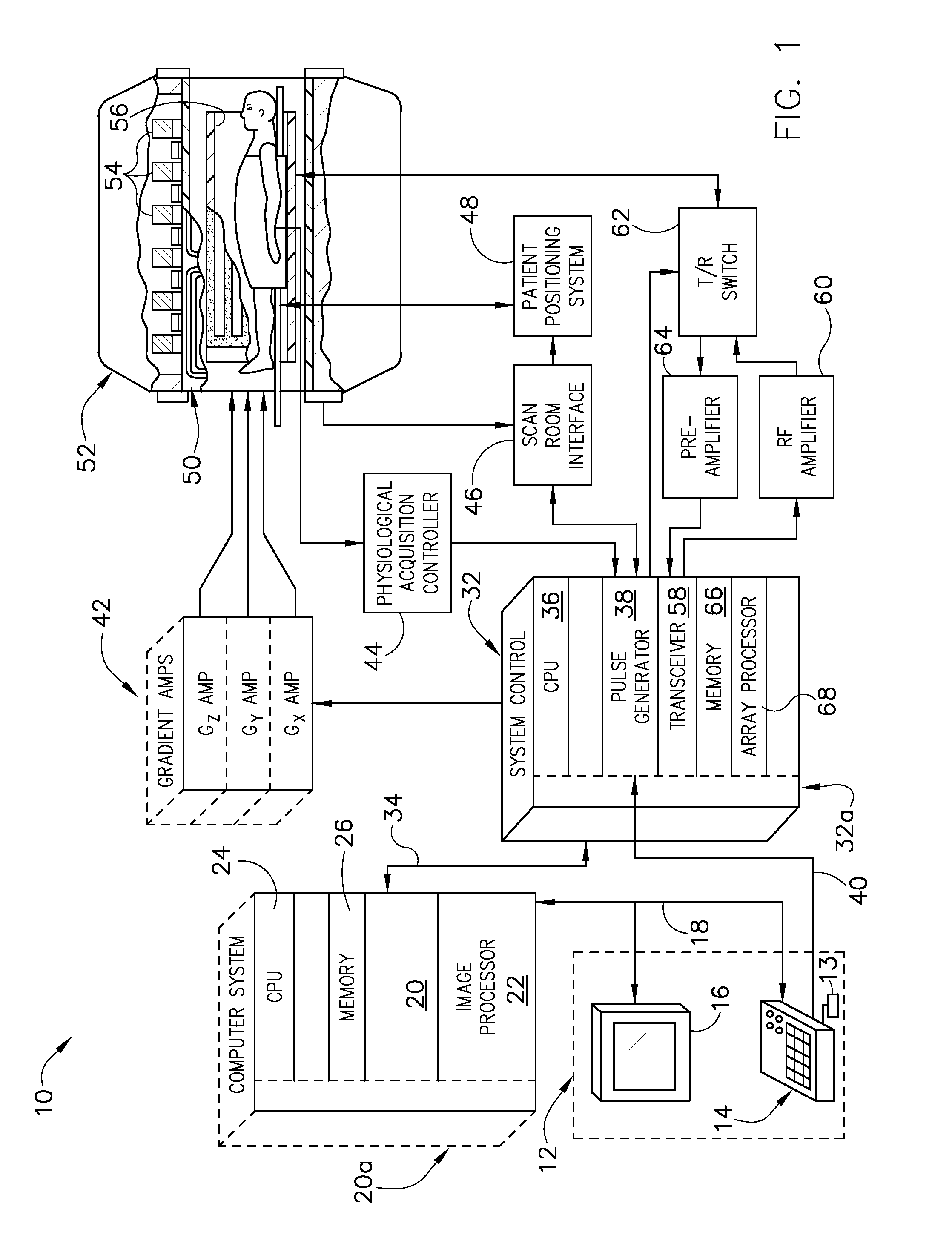
[0018]Referring to FIG. 1, the major components of an exemplary magnetic resonance imaging (MRI) system 10 incorporating embodiments of the present invention are shown. The operation of the system is controlled from an operator console 12 which includes a keyboard or other input device 13, a control panel 14, and a display screen 16. The console 12 communicates through a link 18 with a separate computer system 20 that enables an operator to control the production and display of images on the display screen 16. The computer system 20 includes a number of modules which communicate with each other through a backplane 20a. These include an image processor module 22, a CPU module 24 and a memory module 26 that may include a frame buffer for storing image data arrays. The computer system 20 is linked to archival media devices, permanent or back-up memory storage or a network for storage of image data and programs, and communicates with a separate system control 32 through a high speed ser...


PUM


Abstract

A system and method for MR magnetic field mapping includes a computer programmed to acquire a first data point at a first location in a first phase image data set, a second data point at the first location in a second phase image data set, a third data point at the first location in a third phase image data set. The first, second, and third phase images are acquired using a first, second, and third TE, respectively. Phase wrapping does not occur among the first and second phase image data sets; however, phase wrapping does occur among the second and third phase image data sets. The computer is also programmed to determine a magnetic field inhomogeneity, wherein the determination of the magnetic field inhomogeneity is based on the first, second, and third data points.

Description

BACKGROUND OF THE INVENTION[0001]The present invention relates generally to a three-point method and apparatus for efficiently creating robust magnetic field maps of a region-of-interest (ROI).[0002]When a substance such as human tissue is subjected to a uniform magnetic field (polarizing field B0), the individual magnetic moments of the spins in the tissue attempt to align with this polarizing field, but precess about it in random order at their characteristic Larmor frequency. If the substance, or tissue, is subjected to a magnetic field (excitation field B1) which is in the x-y plane and which is near the Larmor frequency, the net aligned moment, or “longitudinal magnetization”, MZ, may be rotated, or “tipped”, into the x-y plane to produce a net transverse magnetic moment Mt. A signal is emitted by the excited spins after the excitation signal B1 is terminated and this signal may be received and processed to form an image.[0003]When utilizing these signals to produce images, mag...

Claims


Application Information

Patent Timeline
Patent Type & Authority Applications(United States)
IPC IPC(8): G01R33/54
CPCG01R33/243G01R33/56563G01R33/56554G01R33/5616
Inventor AKSIT, PELINDERBYSHIRE, JOHN ANDREW
Owner GENERAL ELECTRIC CO
Why Eureka
Try Eureka