
Illuminator for a Photolithography Device

Active Publication Date: 2009-10-15
SAFRAN ELECTRONICS & DEFENSE
View PDF12 Cites 8 Cited by
  • Summary
  • Abstract
  • Description
  • Claims
  • Application Information

AI Technical Summary

Benefits of technology

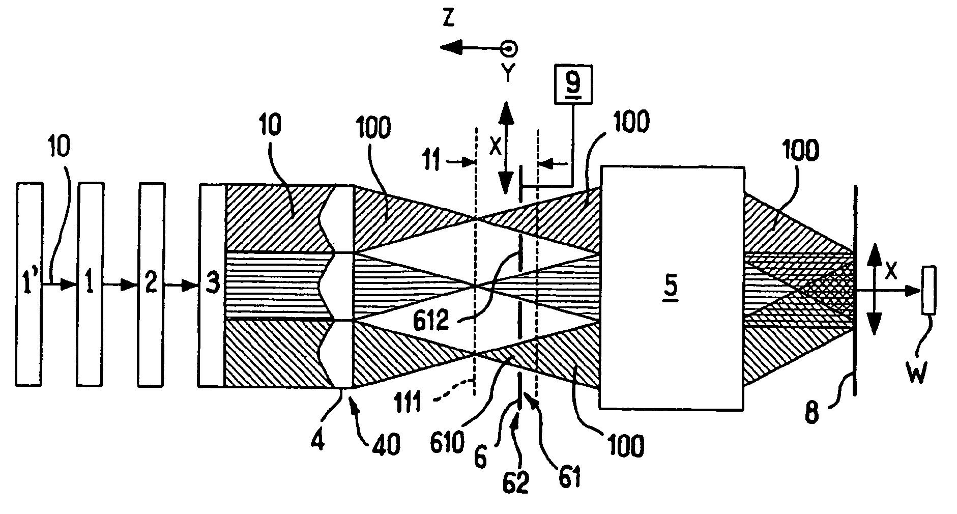
[0037]First, an illuminator according to the invention is simpler and therefore less expensive, due to the absence of a group forming an optical relay in order to conjugate the plane of the shutter and the mask.
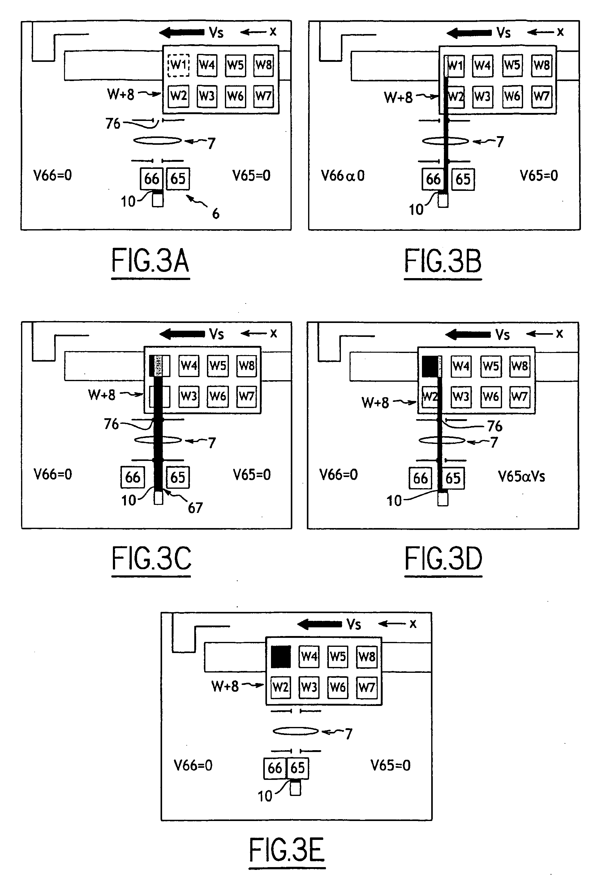
[0038]In addition, the mechanical elements enabling the movement of the mobile plates, one with respect to another, are also simpler and therefore less expensive, due to the reduction in amplitude of the course and the speed of translation of the plates. One may expect a reduction by a factor of 10 in the speed of movement of the plates of the shutter, which allows for a reduction in vibrations produced in the photolithography device as well as a simplification of the means for moving the shutter.
[0039]An illuminator according to the invention makes it possible in particular to correct certain defects of the illumination due to the nature of the illumination source, in particular when the source is a laser. An illuminator according to the invention makes it possible to obtain a trapezoidal illumination profile according to the direction of movement of the mask and the wafer.
[0040]An illuminator according to the invention also in particular allows for a clean cut of the illumination.

Problems solved by technology

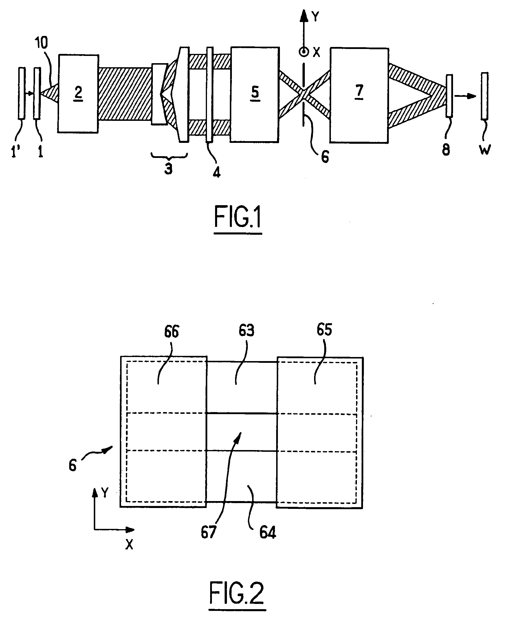
The illuminator according to the prior art is complicated and expensive to produce, in particular due to the presence of a group 7 forming an optical relay for conjugating the plane of the shutter and the mask.
The complexity of such a group is both optical and mechanical.
In addition, the mechanical elements making it possible to move the mobile plates of the shutter are complex and expensive, due to the large amplitude of the course and the high speed of translation of the plates (around 160 mm / s).

Method used


Image

  • Illuminator for a Photolithography Device
  • Illuminator for a Photolithography Device
  • Illuminator for a Photolithography Device

Examples


Embodiment Construction

[0032]The invention is intended to overcome at least one of these disadvantages.

[0033]To this end, the invention proposes an illuminator according to claim 1.

[0034]The invention is advantageously complemented with the features presented in the dependent claims.

[0035]The invention also relates to a device comprising such an illuminator.

[0036]The invention has numerous advantages.

[0037]First, an illuminator according to the invention is simpler and therefore less expensive, due to the absence of a group forming an optical relay in order to conjugate the plane of the shutter and the mask.

[0038]In addition, the mechanical elements enabling the movement of the mobile plates, one with respect to another, are also simpler and therefore less expensive, due to the reduction in amplitude of the course and the speed of translation of the plates. One may expect a reduction by a factor of 10 in the speed of movement of the plates of the shutter, which allows for a reduction in vibrations produce...


PUM


Abstract

The invention relates to an illuminator for a photolithography device. The invention comprises: a source (1′) of a light beam (10) which is used to illuminate a mask (8) and to expose an area of a wafer (W); at least one main array (4) of microlenses; and a shutter (6) consisting of at least one shutter plate (61) comprising at least one part (612) that is opaque to the light beam (10) and a plurality of parts (610) that are transparent to the beam, whereby said plate (61) can be moved in relation to the beam (10) along a direction of movement (X) that is essentially parallel to the plate, such that the opaque part (612) can at least partially block the light beam or such that the transparent parts can at least partially enable the passage of the light beam (10). The invention is characterised in that it comprises movement means (9) which can move the shutter (6) in synchronism with the movements of the mask (8) and the wafer (W), said shutter (6) being located in an area (11) close to a pupil (40, 410) of an optical system comprising at least the main array (4) of microlenses. The invention also relates to a photolithography device comprising one such illuminator.

Description

GENERAL TECHNICAL FIELD[0001]The present invention relates to an illuminator for a photolithography device, as well as such a device.PRIOR ART[0002]Photolithography, also called “microlithography”, has been used for many years to produce semiconductor devices, and, for this purpose, uses electromagnetic radiation to generate fine patterns on semiconductor devices. To this end, an illuminator for a photolithography device illuminates a mask, of which the image is projected onto a semiconductor wafer, which provides a circuit after an ad hoc treatment known to a person skilled in the art.[0003]As shown in FIG. 1, the illumination system, which will be referred to as an “illuminator” in the remainder of the description, for a photolithography device is complex. It must take into account a plurality of parameters simultaneously in order to satisfy the microlithography requirements. The parameters concerned are in particular:[0004]the illumination profile in the pupil of the device;[0005...

Claims


Application Information

Patent Timeline
IPC IPC(8): G03B27/72
CPCG03F7/70066G03F7/7055G03F7/70083G03F7/70125G03F7/70191G03F7/70208
Inventor BOUTONNE, MIGUELMERCIER YTHIER, RENAUDRIGUET, FRANCOIS
Owner SAFRAN ELECTRONICS & DEFENSE
Learn More